Clamping device

A technology of clamping device and receiving sleeve, which is applied in the direction of portable mobile devices, accessories of tool holders, chucks, etc., and can solve problems such as receivability

Active Publication Date: 2013-04-17
NANJING CHERVON IND
View PDF5 Cites 8 Cited by
  • Summary
  • Abstract
  • Description
  • Claims
  • Application Information

AI Technical Summary

Problems solved by technology

However, for tools with tool handles that are larger than the size of the hexagonal shank, such as the common SDS-Plus type and 1 / 4" hexagonal shank type in the market, the receiving sleeves cannot all be accepted.

Method used


Image

  • Clamping device
  • Clamping device
  • Clamping device

Examples


Embodiment Construction

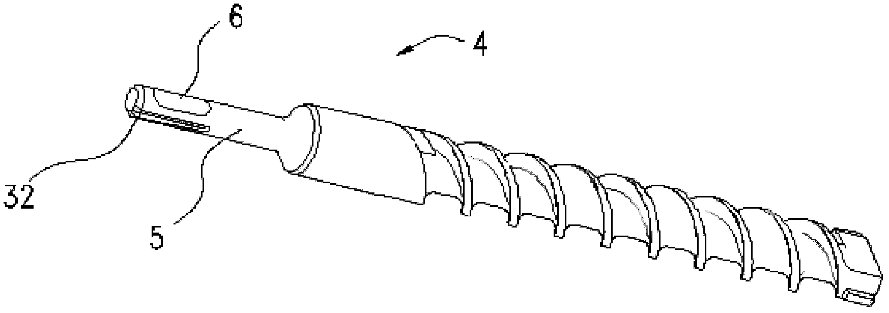
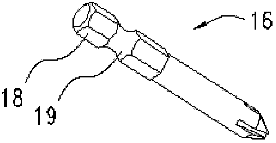
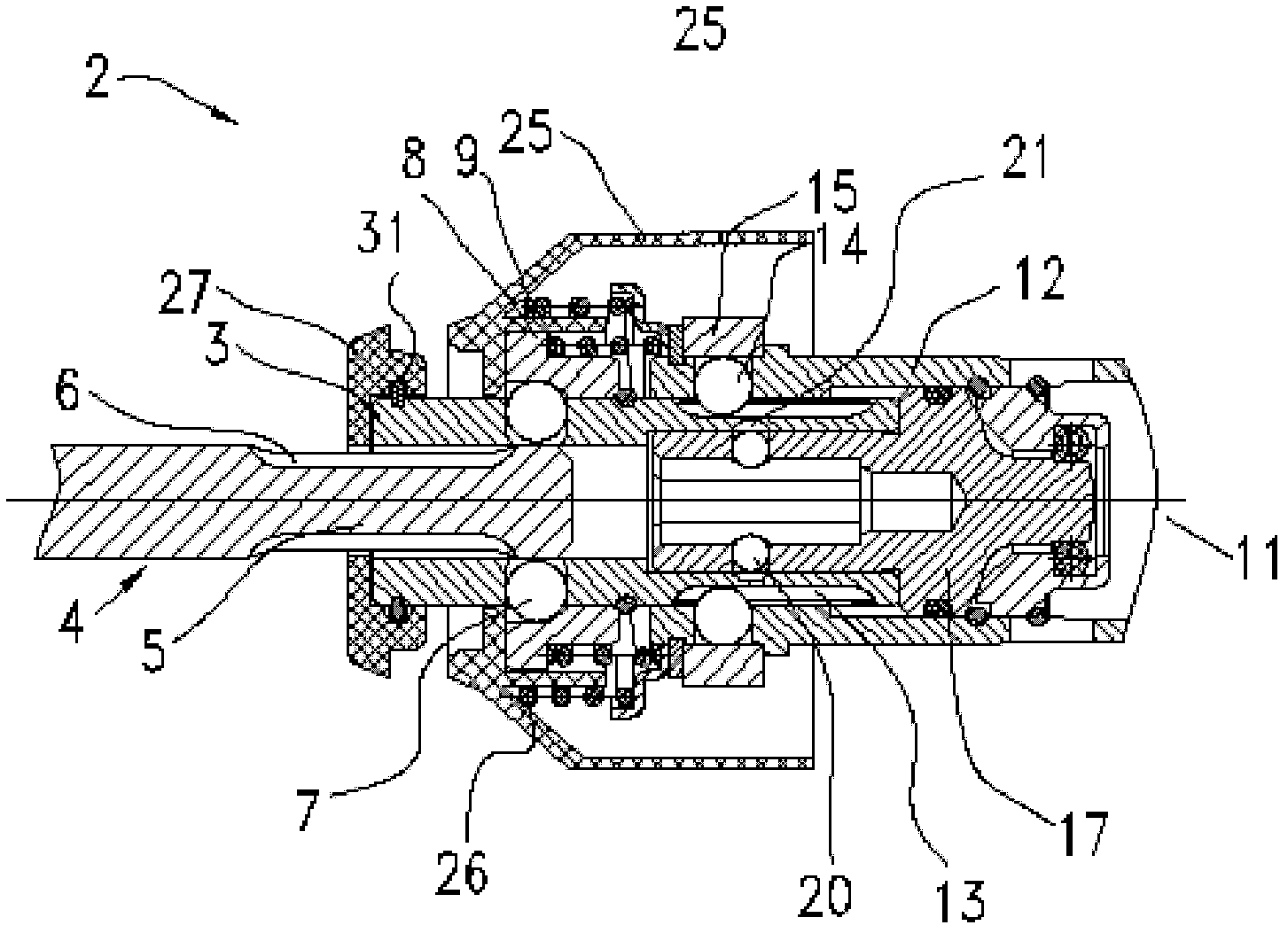
[0019] together with reference Figure 1 to Figure 12 As shown, the clamping device of the present invention is applied to an electric tool with a hammer tube. The clamping device 2 includes: a first receiving sleeve 3 for accommodating the first working head. A working handle that is matched with the receiving sleeve 3; a second receiving sleeve 17 is used to accommodate the second working head, and the second working head has a working handle that cooperates with the second receiving sleeve 17; wherein the first working handle has a difference In terms of the shape of the second working handle, for example: the first receiving sleeve 3 can be plugged and fitted with the SDS-Plus type working head 4, and the second receiving sleeve 17 can be plugged and fitted with the HEX type working head 16. The first receiving sleeve 3 and the hammer tube 12 in the tool holder 1 are connected to each other through the first transmission structure, and the first receiving sleeve 3 and the ...


PUM


Abstract

The invention provides a clamping device applied to an electric tool with a hammer tube. The clamping device comprises a first receiving sleeve and a second receiving sleeve which are connected in matching driving mode, and working heads of tool handles with different sizes can be connected between the first receiving sleeve and the second receiving sleeve in inserting mode. The clamping device enables a tool clamp of a hammer drill to clamp SDS-Plus type and HEX type working heads with different sizes, and achieves the multipurpose efficacy.

Description

【Technical field】 [0001] The invention relates to a clamping device, in particular to a clamping device capable of clamping SDS-Plus and HEX working heads. 【Background technique】 [0002] In known hammer drills, the hammer drill has a tool holder provided with a rotatably driven receiving sleeve formed in one piece, which forms the boundary of a recess open at both ends for the Receives the shank of the plug-in tool used. In order to axially lock the shank, a locking ball is usually provided in the receiving sleeve, also called hammer tube, which is fitted in the plug-in type by means of a spring-loaded locking ring surrounding the receiving sleeve. Behind one of the undercuts of the tool. For the rotary drive, the shank of the plug-in tool has a non-cylindrical cross-section, for example a so-called "SDS-Plus" profile has two diametrically opposite ends extending in the longitudinal direction of the shank. And driving grooves open towards the rear end, when the plug-in t...

Claims


Application Information

Patent Timeline
Patent Type & Authority Applications(China)
IPC IPC(8): B25D17/08B25F3/00
CPCB23B31/008B23B31/1071B23B2231/0232B25D17/088B25D2217/0007B25D2217/0042B25D2250/301
Inventor 乐军
Owner NANJING CHERVON IND
Why Eureka
Try Eureka