Jet printing unit

A technology of nozzle holes and components, applied in the field of printing units, can solve the problems of waste of money and time, poor printing quality, and inability to complete the printing action smoothly.

Inactive Publication Date: 2014-12-10
MICROJET TECH
View PDF8 Cites 0 Cited by
  • Summary
  • Abstract
  • Description
  • Claims
  • Application Information

AI Technical Summary

Problems solved by technology

[0006] The main purpose of the present invention is to provide a jet printing unit to solve the problem that ink cannot pass through the main flow channel due to gas barrier during the printing process of the known jet printing unit, resulting in that the jet printing action cannot be completed smoothly, resulting in poor printing quality, And cause disadvantages such as waste of money and time

Method used


Image

  • Jet printing unit
  • Jet printing unit
  • Jet printing unit

Examples


Embodiment Construction

[0051] Some typical embodiments embodying the features and advantages of the present invention will be described in detail in the description in the following paragraphs. It should be understood that the present invention can have various changes in different aspects, but none of them depart from the scope of the present invention, and the descriptions and drawings therein are used for illustration in nature, not for limit the invention.

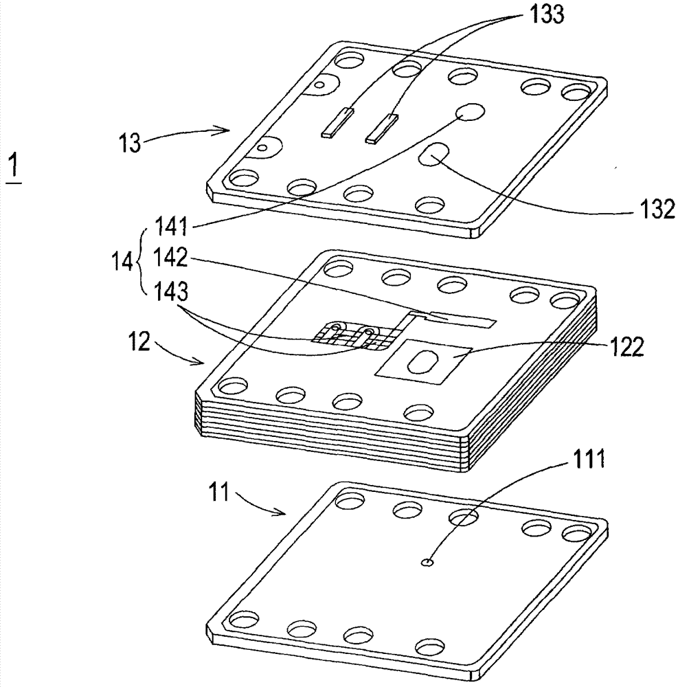
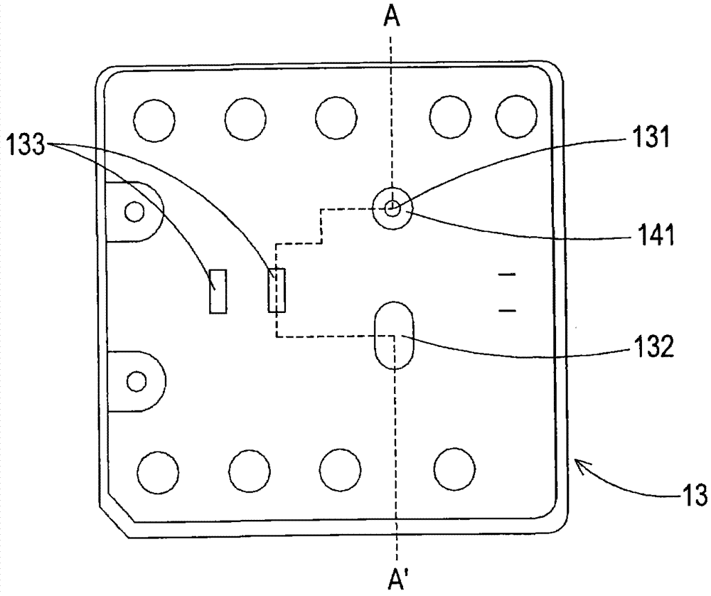
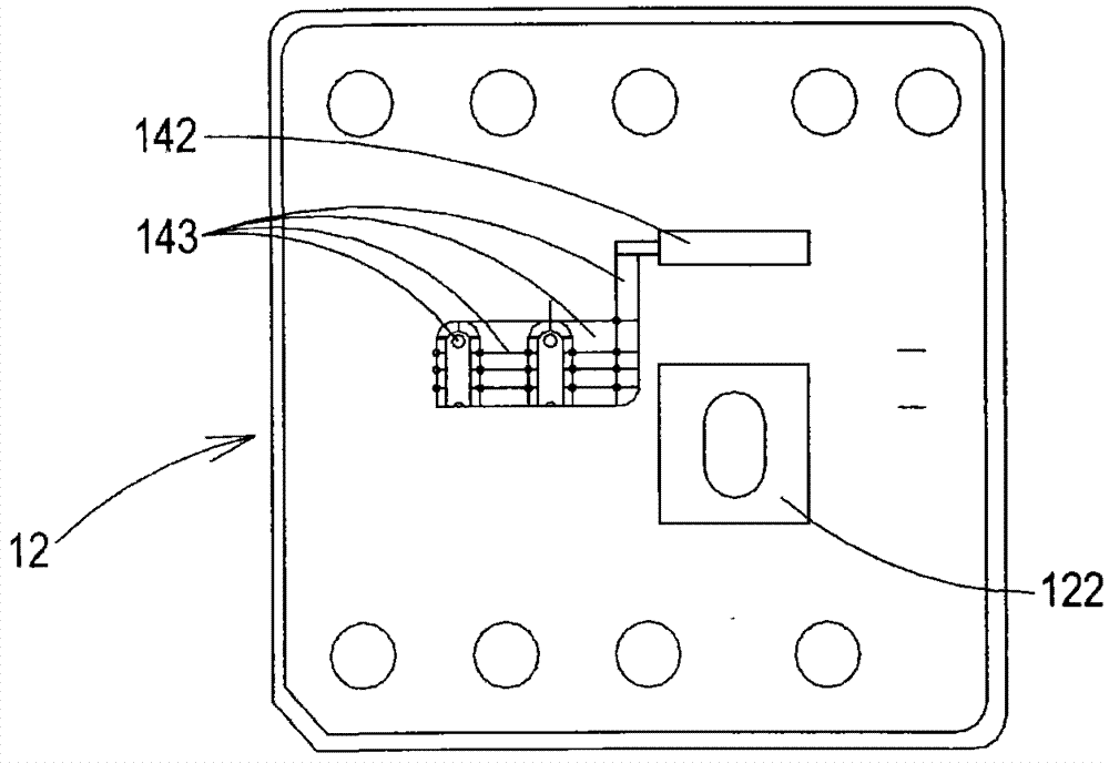
[0052] see figure 1 , figure 2 , image 3 , Figure 4 as well as Figure 5 ,in figure 1 It is a schematic structural diagram of a spray printing unit in a preferred embodiment of the present invention, figure 2 Department of figure 1 A schematic diagram of the vibrating plate and membrane is shown, image 3 Department of figure 1 The schematic diagram of the plate body, the exhaust communication groove and the micro flow channel shown, Figure 4 Department of figure 1 The schematic diagram of the orifice plate is shown, and Fi...


PUM


Abstract

The invention relates a jet printing unit which at least comprises an orifice plate, a plate body, an oscillating plate and runner exhaust elements, wherein the plate body is arranged to be adjacent to the orifice plate and is provided with a runner, the oscillating plate is arranged on the plate body and is provided with an exhaust hole, partial runner exhaust elements are arranged between the oscillating plate and the plate body, and each runner exhaust element at least comprises a film arranged and covers on an exhaust hole, an exhaust communicating groove communicated with the exhaust hole, and a microrunner arranged between the runner and the exhaust communicating groove and communicated with the runner and the exhaust communicating groove to ensure that gas flows to the exhaust communicating groove and is exhausted through the exhaust hole through the film. By means of the communication of the runner, the microrunners, the exhaust communicating grooves and the films, the gas in the runners is exhausted, and the effects of maintaining jet printing quality and reducing money and time waste are achieved.

Description

technical field [0001] The invention relates to a jet printing unit, especially a jet printing unit capable of removing air bubbles in a flow channel and maintaining the quality of jet printing. Background technique [0002] In recent years, with the vigorous development of personal computers and industrial technology, the combination of technology and daily life has become closer. Printing equipment has become an indispensable product around personal computers in enterprises or families. Among them, inkjet printers It has the advantages of low price, simple replacement and easy acquisition of consumables, so it is widely used by consumers. [0003] Known ink-jet printers mainly carry out the printing action by the ink-jet head, and the printing unit on the ink-jet head is arranged on the ink cartridge, which is formed by stacking multi-layer objects, including an orifice plate with nozzles, a vibrating Boards and multi-layer boards, etc., to form the main flow channel. Th...

Claims


Application Information

Patent Timeline
Patent Type & Authority Patents(China)
IPC IPC(8): B41J2/01
Inventor 奚国元黄科铭戴贤忠
Owner MICROJET TECH
Why Eureka
Try Eureka