Automatic trigger broken belt capturing device for belt conveyer

A broken belt catching device and belt conveyor technology, applied in the conveyor control device, conveyor objects, transportation and packaging, etc., can solve the problems of belt impact damage, secondary belt damage, unreliable triggering, etc. The effect of smooth braking process, reliable work and safe and reliable action process

Active Publication Date: 2013-04-17
CHINA UNIV OF MINING & TECH +1
View PDF5 Cites 16 Cited by
  • Summary
  • Abstract
  • Description
  • Claims
  • Application Information

AI Technical Summary

Problems solved by technology

[0002] The currently used broken belt arresting devices have the following problems: most of them rely on additional power sources to drive, requiring the equipment to be in operation all the time, resulting in high energy consumption and heavy wear; some of them use backstop rollers to achieve automatic triggering, which has the problem of unreliable triggering ; Simultaneously, when many arresting devices complete the arrest, the belt and the arrester are in line contact or only catch the edge of the belt, which will easily cause the belt to tear; in addition, most of the existing arresting devices directly connect the belt and transport The bulk material is pressed in the catcher, and the hard material will also cause secondary damage to the belt; finally, when the current catcher catches a broken belt, it is mostly directly locked, which is easy to cause impact damage to the belt

Method used


Image

  • Automatic trigger broken belt capturing device for belt conveyer
  • Automatic trigger broken belt capturing device for belt conveyer
  • Automatic trigger broken belt capturing device for belt conveyer

Examples


Embodiment Construction

[0027] An embodiment of the present invention will be further described below in conjunction with accompanying drawing:

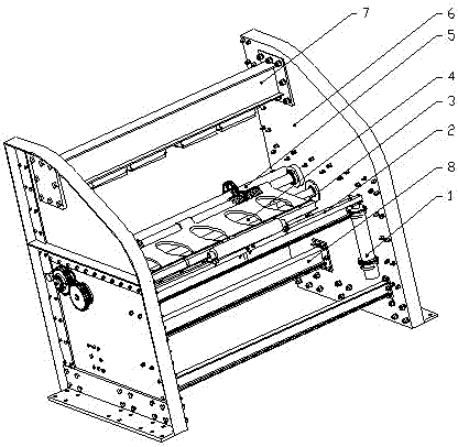
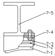
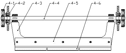
[0028] Such as figure 1 with figure 2 As shown, the belt conveyor of the present invention uses an automatic triggering and catching device, mainly consisting of a trigger mechanism 1, a carrying mechanism 2, an upper braking mechanism 3, a lower braking mechanism 4, a moment loading mechanism 5, a frame side plate 6, The upper brake beam mechanism 7, the lower brake beam mechanism 8, the locking mechanism 9 and the crossbeam 10 constitute. Wherein the frame is composed of two frame side plates 6 connected by a plurality of crossbeams 10, the upper brake mechanism 3 is installed in the middle of the frame, the trigger mechanism 1, the carrying mechanism 2 and the locking mechanism 9 are installed in the front of the upper brake mechanism 3, and the rear is installed There is a torque loading mechanism 5, a lower brake mechanism 4 is installed below, an u...


PUM


Abstract

An automatic trigger broken belt capturing device for a belt conveyer comprises a machine frame formed by two machine frame lateral plates, wherein an upper braking mechanism is arranged in the middle of the machine frame, a trigger mechanism and a locking mechanism are arranged in the front of the upper braking mechanism, a torque loading mechanism is arranged behind the upper braking mechanism, a lower braking mechanism is arranged below the upper braking mechanism, an upper braking beam mechanism is arranged above the upper braking mechanism, a lower braking beam is arranged below a lower braking beam, and the whole capturing device is in the to-start state under driving of energy stored by a torsion spring and a compressed spring. Once belt breaking happens, the trigger mechanism and a bearing mechanism act to lead the locking mechanism to be unlocked, the upper braking mechanism and the lower braking mechanism simultaneously act, and an upward belt and a downward belt are respectively braked through the eccentric self-locking principle. The automatic trigger broken belt capturing device is simple in structure, high in capturing success rate, uniform in capturing force, small in impact, economical, reasonable, convenient to maintain and capable of being automatically triggered without being driven by a power source.

Description

technical field [0001] The invention relates to an automatic trigger arresting device for a belt conveyor, especially suitable for a belt conveyor for transporting a large amount of bulk materials. Background technique [0002] The currently used broken belt arresting devices have the following problems: most of them rely on additional power sources to drive, requiring the equipment to be in operation all the time, resulting in high energy consumption and heavy wear; some of them use backstop rollers to achieve automatic triggering, which has the problem of unreliable triggering ; Simultaneously, when many arresting devices complete the arrest, the belt and the arrester are in line contact or only catch the edge of the belt, which will easily cause the belt to tear; in addition, most of the existing arresting devices directly connect the belt and transport The bulk material is pressed in the catcher, and the hard material will also cause secondary damage to the belt; finally...

Claims


Application Information

Patent Timeline
Patent Type & Authority Applications(China)
IPC IPC(8): B65G43/06
Inventor 朱真才张磊陈利强张衍阳周公博李伟彭玉兴沈刚
Owner CHINA UNIV OF MINING & TECH
Why Eureka
Try Eureka