

Pneumatic rotary joint
A technology of rotary joints and inflatable joints, applied in the direction of pipe components, etc., can solve the problems that the inflatable path and the vacuumed path are parallel and uniform around the rotating mechanism, leakage, and do not have the fusion of inflated and vacuumized, etc., to achieve enhanced sealing performance, simple connection and easy maintenance
- Summary
- Abstract
- Description
- Claims
- Application Information
AI Technical Summary
Problems solved by technology
Method used
Image

Examples
Embodiment 1
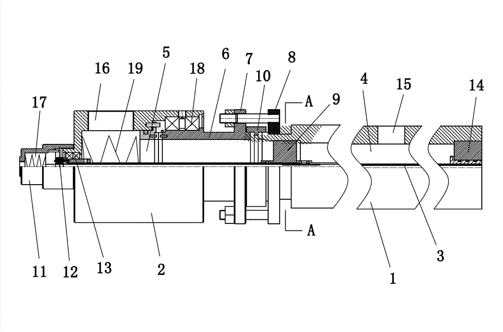
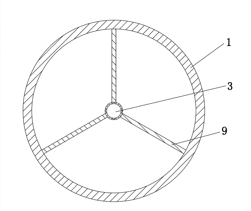
[0020] Embodiment 1: as figure 1 , 2 As shown, a gas rotary joint includes a rotary main shaft 1 and a joint main body 2, and the rotary main shaft 1 and the joint main body 2 are located on the same axis. The interior of the rotating spindle 1 is hollow with a first vacuum chamber 4, the joint body 2 includes a shell, and the inside of the shell has a second vacuum chamber 5, and a vacuum interface 16 is opened on the joint body 2, and the vacuum joint 16 is connected to the inside of the joint body 2. The second vacuum chamber 5 is connected; a vacuum outlet 15 is opened on the rotating main shaft 1 , and the vacuum outlet 15 is connected to the first vacuum chamber 4 inside the rotating main shaft 1 . A fixed connecting sleeve 6 is installed at one end of the joint body 2 close to the rotating main shaft 1, and the end of the fixed connecting sleeve 6 away from the rotating main shaft 1 is located inside the joint main body 2, and the fixed connecting sleeve 6 is connected...
PUM
 Abstract
Description
Claims
Application Information