Connector

A connector and electrical connection technology, which is applied in the direction of connection, fixed connection, and parts of the connection device, etc., can solve the problems of displacement of the arrangement direction, inability to ensure contact stability, inability to follow the tilting action of the connector 901, etc. The effect of improving durability and contact reliability

Active Publication Date: 2013-04-17
JAPAN AVIATION ELECTRONICS IND LTD
View PDF7 Cites 38 Cited by
  • Summary
  • Abstract
  • Description
  • Claims
  • Application Information

AI Technical Summary

Problems solved by technology

Therefore, for example, when the manufacturing precision of the connector 901 and the counterpart connector 930 is low, sometimes the predetermined contact force of the first, second, and third contact portions 918a, 918b, and 918c cannot be obtained. Unable to ensure contact stability
[0007] In addition, in the conventional connector 901, when the connector 901 is inserted into the mating portion 934a of the mating connector 930 with rocking (shaking up, down, left, and right), since the first, second, and third contacts Parts 918a, 918b, 918c can hardly be displaced along the arrangement direction of the first, second, third contact spring parts 917a, 917b, 917c, so the first, second, third contact parts 918a, 918b, 918c cannot follow Tilt action of connector 901
As a result, the fixed ends of the first, second, and third contact spring portions 917a, 917b, and 917c that are continuous with the holding plate portion 913 of the contact plate portion 911 may be plastically deformed.

Method used


Image

  • Connector
  • Connector
  • Connector

Examples


Embodiment Construction

[0048] Hereinafter, embodiments of the present invention will be described based on the drawings.

[0049] First, based on Figure 1 to Figure 23 The first embodiment of the present invention will be described.

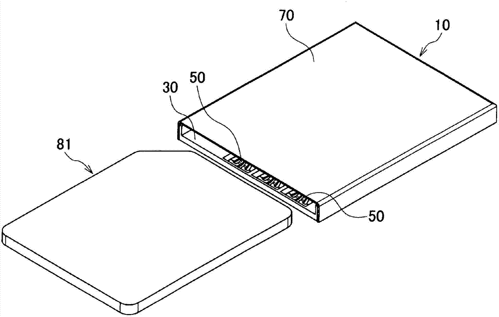
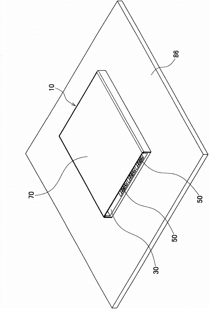
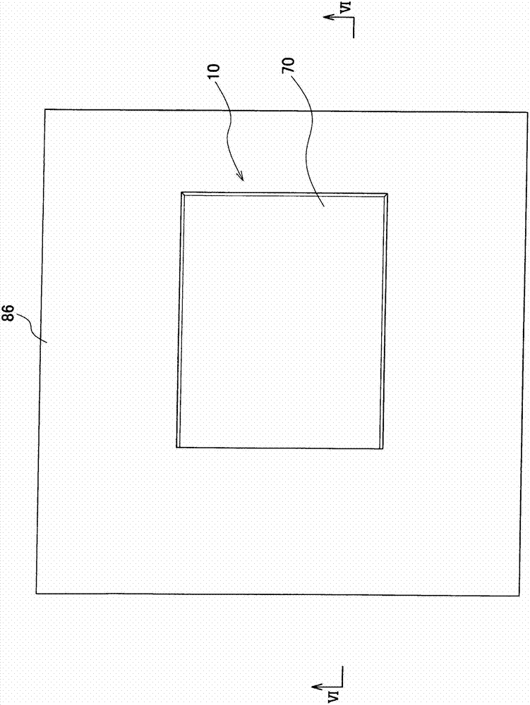
[0050] Such as figure 1 , figure 2 , image 3 As shown, the connector 10 electrically connects a card-type electronic component (first connection object) 81 and a printed circuit board (second connection object) 86 .

[0051] The connector 10 includes a housing 30 , six contacts 50 , and a cover 70 .

[0052] Such as Figure 4 As shown, the housing 30 is in the shape of a shell whose front and upper portions are open, and has a bottom portion 31 , two side wall portions 32 , and a rear wall portion 33 . The bottom portion 31 has a flat plate shape, and the card-type electronic component 81 is disposed on the bottom portion 31 . The arrangement surface 82 of the bottom portion 31 and the card-type electronic component 81 (refer to Figure 19 )relatively. Six...


PUM


Abstract

A connector capable of improving the durability and the contact reliability of a contact. In the contact, a pair of spring portions for pressing a contact portion against a card-type electronic component are formed continuous with the contact portion that is brought into contact with the card-type electronic component. A holding portion held by a housing is formed continuous with the spring portions A connection portion connected to a printed board is formed continuous with the holding portion. The spring portions are made elastically deformable independently of each other, and are bent such that part and the other part of each spring portion do not interfere with each other in a direction of height of the housing when the spring portion is elastically deformed.

Description

technical field [0001] The present invention relates to connectors. Background technique [0002] In the past, such as Figure 28 As shown, a connector 901 including an insulator 903 and a contact 910 held by the insulator 903 is known (refer to Japanese Patent Application Laid-Open No. 10-32031 (paragraphs 0015, 0022, 0023, 0025, figure 1 , figure 2 , Figure 4 Wait)). in addition, Figure 28 , Figure 29 , Figure 30 Respectively with Japanese Patent Application Publication No. 10-32031 figure 1 , figure 2 , Figure 4 Corresponding. but, Figure 28 , Figure 29 , Figure 30 The reference numerals in are changed, and part of the reference numerals are deleted. [0003] Each contact 910 has a contact plate portion 911 , a holding plate portion 913 and a terminal portion 915 . The contact plate portion 911 extends toward the fitting opening 903 d side of the insulator 903 . The holding plate portion 913 is held on the bottom 903 b of the insulator 903 . The ...

Claims


Application Information

Patent Timeline
Patent Type & Authority Applications(China)
IPC IPC(8): H01R13/24H01R13/40H01R12/71
CPCH01R12/57H01R12/716H01R13/245H01R12/71H01R13/2457H01R13/11
Inventor 佐藤雄三
Owner JAPAN AVIATION ELECTRONICS IND LTD
Why Eureka
Try Eureka