Control circuit for reducing electromagnetic interference

一种控制电路、电磁干扰的技术,应用在减少电器干扰、功率的自动控制、减少由正弦振荡引起的干扰等方向,能够解决实现复杂等问题

Active Publication Date: 2013-04-17
MACROBLOCK INC
View PDF7 Cites 4 Cited by
  • Summary
  • Abstract
  • Description
  • Claims
  • Application Information

AI Technical Summary

Problems solved by technology

This approach realizes 2n reference voltages with resistor strings, and uses multiple switches to complete the output selection voltage of the voltage control unit, which is more complicated in implementation

Method used


Image

  • Control circuit for reducing electromagnetic interference
  • Control circuit for reducing electromagnetic interference
  • Control circuit for reducing electromagnetic interference

Examples


Embodiment Construction

[0051] Below in conjunction with accompanying drawing, structural principle and working principle of the present invention are specifically described:

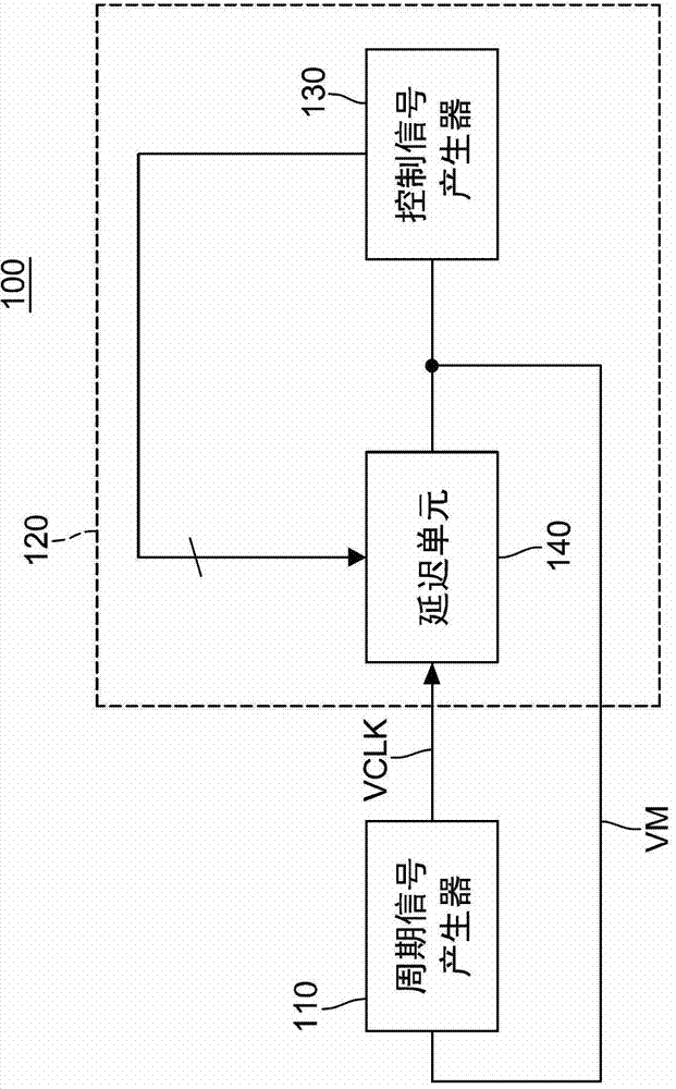
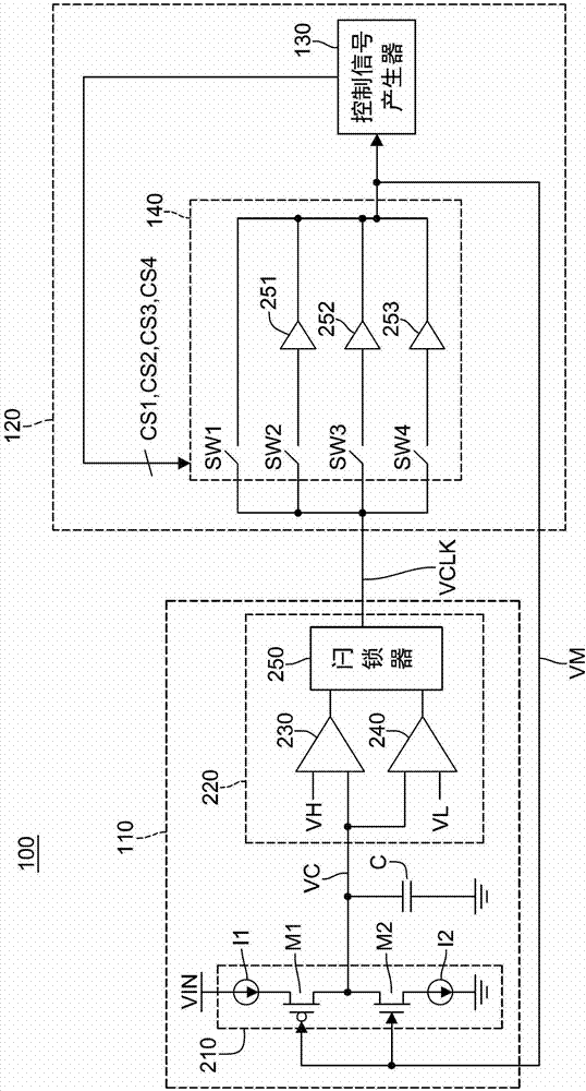
[0052] Please refer to figure 1 As shown, it is a circuit block diagram of the control circuit for reducing electromagnetic interference of the present invention. The control circuit 100 for reducing electromagnetic interference includes a periodic signal generator 110 and a modulation controller 120 .

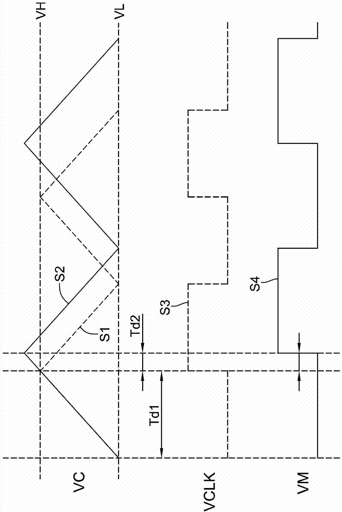
[0053] The periodic signal generator 110 is used for modulating the output signal of the periodic signal generator 110 into the modulated periodic signal VCLK according to the feedback modulation signal VM. The modulation controller 120 is coupled to the periodic signal generator 110, receives the modulated periodic signal VCLK, and provides a plurality of different delay times to modulate the frequency of the aforementioned modulated periodic signal VCLK according to a plurality of control signals to generate feedback. modula...


PUM


Abstract

A control circuit for reducing electromagnetic interference is provided. The control circuit includes a periodic signal generator and a modulation controller. The periodic signal generator adjusts a modulation periodic signal generated by the periodic signal generator, according to a feedback modulation signal. The modulation controller is coupled to the periodic signal generator, for receiving the modulation periodic signal, and adjusting a frequency of the received modulation periodic signal according to a plurality of delay periods set according to a plurality of control signals, and generating the feedback modulation signal.

Description

technical field [0001] The invention relates to a circuit for reducing electromagnetic interference, in particular to a control circuit for reducing electromagnetic interference. Background technique [0002] With the development of digital technology, in order to support high-density and high-speed information transmission, digital systems need a reliable and accurate clock generator to generate high-frequency clock signals as a reference for data signal transmission rates. The generation and distribution of a typical system timing clock is composed of a series of functional components. This series of functional components can be IC semiconductor chips such as component chipsets or independently packaged highly integrated components, and these IC semiconductor chips are resistant to electromagnetic interference ( Electromagnetic Interference, EMI) is very sensitive. [0003] The high-frequency clock signal generated by the clock generator often causes electromagnetic inter...

Claims


Application Information

Patent Timeline
Patent Type & Authority Applications(China)
IPC IPC(8): H02M1/44
CPCH04B15/04H03L7/00
Inventor 郑又文蔡宗达
Owner MACROBLOCK INC
Why Eureka
Try Eureka