Circuit control method and device

A technology of circuit control and control method, applied in the direction of output power conversion device, electrical components, etc., can solve the problems of low circuit operation efficiency, and achieve the solution of low circuit operation efficiency, reduce electromagnetic interference phenomenon, and improve circuit operation efficiency. Effect

Active Publication Date: 2018-10-30
CHIPONE TECH BEIJINGCO LTD
View PDF8 Cites 0 Cited by
  • Summary
  • Abstract
  • Description
  • Claims
  • Application Information

AI Technical Summary

Problems solved by technology

[0004] Embodiments of the present invention provide a circuit control method and device to at least solve the technical problem of low circuit operation efficiency caused by electromagnetic interference in the prior art

Method used


Image

  • Circuit control method and device
  • Circuit control method and device
  • Circuit control method and device

Examples


Embodiment 1

[0034] According to an embodiment of the present invention, an embodiment of a circuit control method is provided. It should be noted that the steps shown in the flowcharts of the accompanying drawings can be executed in a computer system such as a set of computer-executable instructions, and, although A logical order is shown in the flowcharts, but in some cases the steps shown or described may be performed in an order different from that shown or described herein.

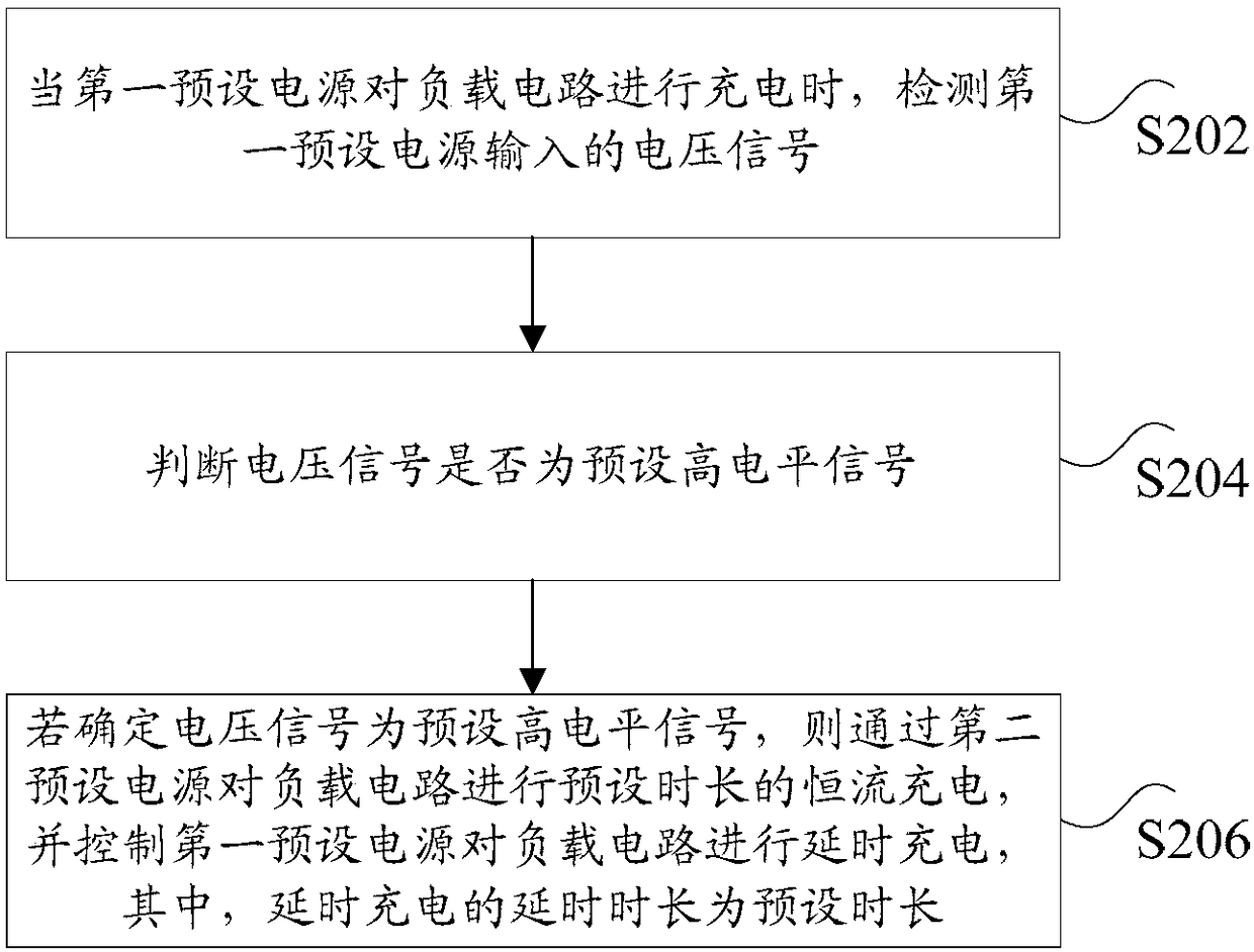
[0035] figure 2 is a circuit control method according to an embodiment of the present invention, such as figure 2 As shown, the method includes the following steps:

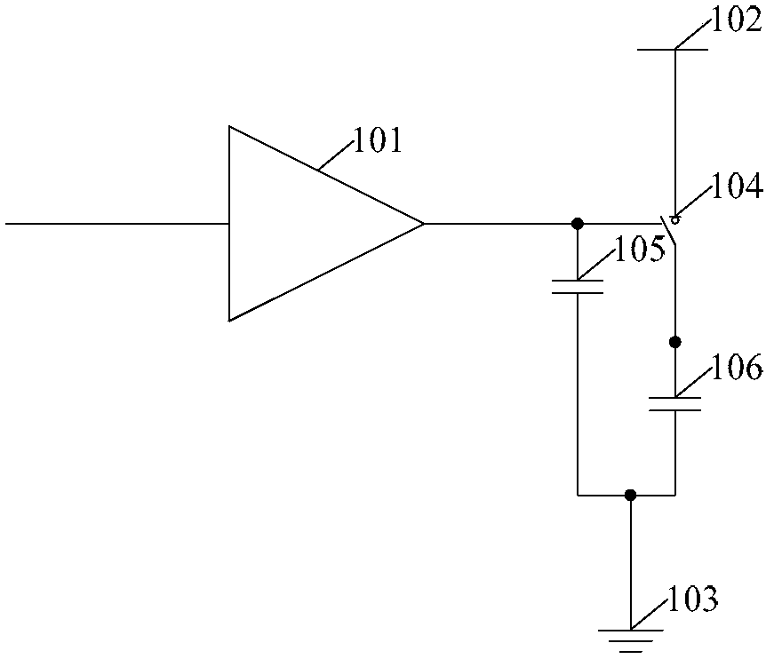
[0036] Step S202, when the first preset power supply charges the load circuit, detect the voltage signal input by the first preset power supply;

[0037] Step S204, judging whether the voltage signal is a preset high-level signal;

[0038] Step S206, if it is determined that the voltage signal is a preset high-level signal, then charge the load...

Embodiment 2

[0059] According to an embodiment of the present invention, a circuit control device is also provided, such as Figure 11 As shown, it includes: a first detection unit 1101 , a first judgment unit 1103 , and a first processing unit 1105 .

[0060] Among them, the first detection unit 1101 is used to detect the voltage signal input by the first preset power supply when the first preset power supply is charging the load circuit; the first judging unit 1103 is used to judge whether the voltage signal is preset high level signal; the first processing unit 1105 is used to charge the load circuit with a constant current for a preset duration through the second preset power supply if it is determined that the voltage signal is a preset high level signal, and control the first preset power supply Delayed charging is performed on the load circuit, wherein the delay time of the delayed charging is a preset time length.

[0061] Optionally, as in Figure 12 As shown, the device further...


PUM


Abstract

The invention discloses a circuit control method and apparatus. The method comprises: when a first preset power supply charges a load circuit, a voltage signal inputted by the first power supply is detected; whether the voltage signal is a preset high-level signal is determined; and if so, constant-current charging with a preset time length is carried out on the load circuit by a second preset power supply and the first preset power supply is controlled to carry out time-delay charging on the load circuit, wherein the delayed time length of the time-delay charging is the preset time length. With the method and apparatus, a technical problem of low circuit operation efficiency caused by an electromagnetic interference phenomenon in the prior art can be solved.

Description

technical field [0001] The invention relates to the field of integrated circuits, in particular to a circuit control method and device. Background technique [0002] Switching Mode Power Supply (Switching Mode Power Supply) is a power supply that uses modern power electronics technology to control the time ratio of the switching tube on and off and stabilize the output voltage. Such as figure 1 As shown, the switching power supply drive circuit in the prior art at least includes: a voltage driver 101, a switch power supply connection terminal 102, a ground terminal 103, a switch tube 104, a gate capacitor 105 and a load capacitor 106. When the circuit reaches a steady state , the switch tube 104 needs to reach the maximum conduction state, that is, the equivalent conduction resistance Rdson is the minimum. Generally, the energy will transfer and change when the switch tube 104 is turned on or off, but if the energy transmission is too fast and uncontrollable, it will lead ...

Claims


Application Information

Patent Timeline
Patent Type & Authority Patents(China)
IPC IPC(8): H02M1/088
CPCH02M1/088
Inventor 金宁李东
Owner CHIPONE TECH BEIJINGCO LTD
Why Eureka
Try Eureka