Pneumatic correction device for cell transferring

A calibration device and cell technology, which is applied in the field of solar cells, can solve the problems of reduced precision, generation of debris, and easy deviation of cells, so as to prevent deviation and debris, realize position correction, and ensure synchronous action.

Active Publication Date: 2013-04-24
JA SOLAR TECH YANGZHOU
View PDF7 Cites 8 Cited by
  • Summary
  • Abstract
  • Description
  • Claims
  • Application Information

AI Technical Summary

Problems solved by technology

[0003] The object of the present invention is to provide a pneumatic correction device for cell transmission, the device is set on the walking arm used to transfer the battery, through the pneumatic correction device can correct the position of the battery on the walking arm, to solve the problems in the prior art The precision reduction problem caused by the mechanical wear of the walking arm can solve the problem that the cells are easy to deviate and generate debris during the transmission process, and can make the cells centered and corrected during the safe transmission process

Method used


Image

  • Pneumatic correction device for cell transferring
  • Pneumatic correction device for cell transferring

Examples


Embodiment 1

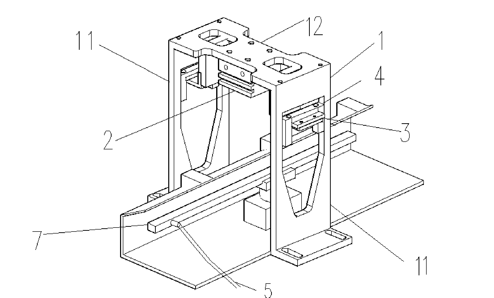
[0018] Such as Figure 1-2 As shown, a pneumatic correction device for cell transmission includes a base 1, a cylinder 2, a combined baffle 3, a U-shaped clamp arm 4, a proximity switch 5 and a sensing element. A pair of side plates 11 on the side and a top plate 12 located on the top of the pair of side plates, the cylinder 2 is arranged below the top plate 12, and the combined baffle plate 3 is a pair, which are symmetrically installed on the guide rods 21 on both sides of the cylinder 2 and located Below the cylinder 2, a pair of U-shaped clamp arms 4 are symmetrically installed on the combined baffle plate 3 respectively. The guide rod 21 shrinks or stretches to drive the movement of the U-shaped clamp arm 4 to correct the position of the battery sheet.

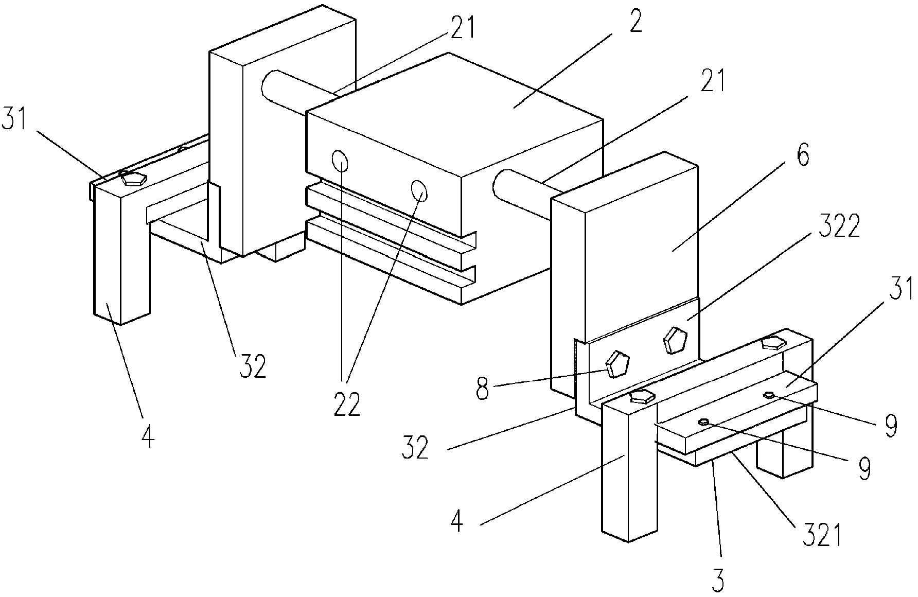
[0019] In order to realize that the pneumatic device can calibrate cells of different sizes on the conveying arm, the combined baffle 3 is composed of an upper baffle 31 and a lower baffle 32, wherein the upper baffle 31...

Embodiment 2

[0028] The difference from Embodiment 1 is that the detachable connection modes of the upper baffle 31 and the flat part 322 of the lower baffle 32 in the combination baffle 3 in this embodiment are different, and the flat part 321 of the lower baffle 32 in this embodiment There are two rows of parallel screw holes, and the upper baffle plate 31 is provided with fixing bolts 9 at positions corresponding to the screw holes. By adjusting the position of the fixing bolt 9 on the upper baffle plate 31 in the first row or the second row of screw holes of the lower baffle plate, the upper baffle plate 31 is positioned at different positions of the lower baffle plate plate portion 322 to realize the U-shaped clamp arm. position adjustment. This is only the preferred detachable mode of the present invention, and other detachable connection modes can be adopted.


PUM


Abstract

The invention discloses a pneumatic correction device for cell transferring. The pneumatic correction device for cell transferring comprises a base, a cylinder, a pair of combination baffles, a pair of U-shaped clamp arms, a proximity switch, and a sensing element. The base comprises a pair of side plates and a top plate located at the top of the side plates. The cylinder is disposed below the top plate. The combination baffles are symmetrically disposed on a guide bar on two sides of the cylinder respectively and located below the cylinder. The U-shaped clamp arms are symmetrically disposed on the combination baffles respectively. The sensing element is connected with an air hole of the cylinder. The proximity switch provides cylinder operation signals through the sensing element so as to allow the guide bar on the cylinder to contract or extend to drive the U-shaped clamp arms to move, thereby correcting the position of a cell. The pneumatic correction device is disposed on a travel arm used for transferring cells. The position of the cells on the travel arm can be corrected by the pneumatic correction device, and accordingly the problems of lower precision and proneness of cells to deflection and fragmentation in transfer process caused by mechanical wear of the travel arm in the prior art are solved.

Description

technical field [0001] The invention belongs to the field of solar cells, and in particular relates to a pneumatic correction device for transferring battery sheets. Background technique [0002] In the printing process of cell production, the BACCINI device that transmits cells moves through the entire walkbeam (traveling arm) (21MG motor front and rear) and (22MG motor up and down) for moving transmission, and the walking arm reciprocates in front and rear of the moving cell During the process, the farthest distance that the walking arm moves in the same direction as the cell running direction is defined as the lower posterior position, and the farthest distance that the walking arm moves in the opposite direction to the cell running direction is defined as the lower front position, WALKBEAM Long-distance repeated transmission, wear and tear of mechanical connecting parts, the precision is not as good as before, which seriously affects the accuracy of transmission. The BA...

Claims


Application Information

Patent Timeline
Patent Type & Authority Applications(China)
IPC IPC(8): B65H5/08B65H29/38
Inventor 王利国刘屹邹会杨杰殷成明
Owner JA SOLAR TECH YANGZHOU
Why Eureka
Try Eureka