
Workpiece Correction System

A technology for correcting systems and workpieces, applied in metal processing machinery parts, manufacturing tools, metal processing, etc., can solve the problems of heavy plate quality, machine damage, and plate collision with the machine, so as to save labor costs, improve work efficiency, The effect of improving the correction accuracy

Active Publication Date: 2022-02-01
HANS LASER TECH IND GRP CO LTD
View PDF10 Cites 0 Cited by
  • Summary
  • Abstract
  • Description
  • Claims
  • Application Information

AI Technical Summary

Problems solved by technology

[0002] Before the plate enters the working area of ​​the bending machine or other plate processing machine tools, due to its heavy weight, the plate needs to be placed on the loading platform with the help of a lifting device. Due to the uncontrollable placement of the operator, the plate may be biased. Moved out of the load platform, making it difficult to access the work area
There are even plates colliding with the machine, causing damage to the machine
[0003] The thicker plate is heavier, and it is difficult to push it by manpower alone.
The current method is to rely on manpower to borrow tools such as crowbars to move the plate to the effective cutting range of the loading platform, which wastes manpower and material resources and has potential safety hazards

Method used


Image

  • Workpiece Correction System
  • Workpiece Correction System
  • Workpiece Correction System

Examples


Embodiment Construction

[0033] In order to facilitate the understanding of the present invention, the present invention will be described more fully below with reference to the relevant drawings. Preferred embodiments of the invention are shown in the accompanying drawings. However, the present invention can be embodied in many different forms and is not limited to the embodiments described herein. Rather, these embodiments are provided so that the understanding of the present disclosure will be better and more comprehensive.

[0034] It should be noted that when an element is referred to as being “fixed” to another element, it can be directly on the other element or there can also be an intervening element. When an element is referred to as being "connected to" another element, it can be directly connected to the other element or intervening elements may also be present. In contrast, when an element is referred to as being "directly on" another element, there are no intervening elements present. ...


PUM


Abstract

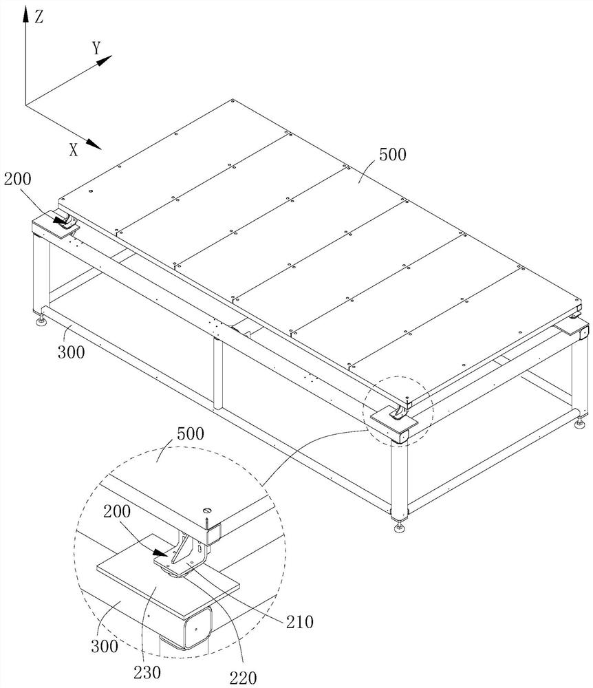
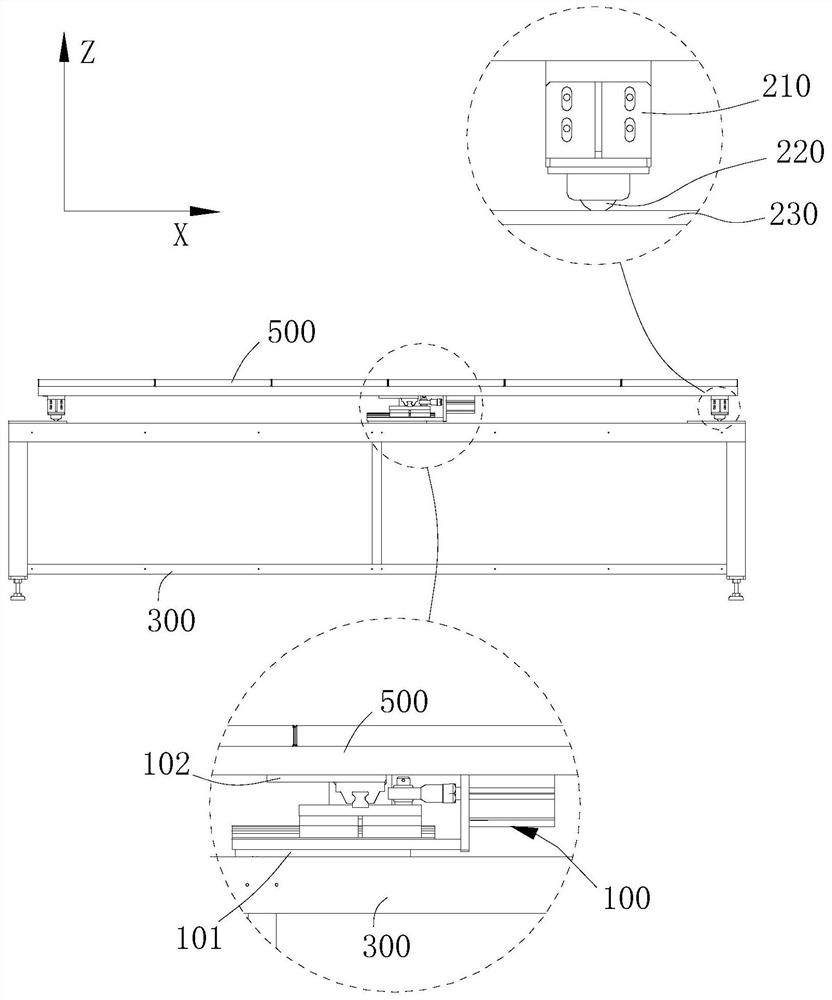
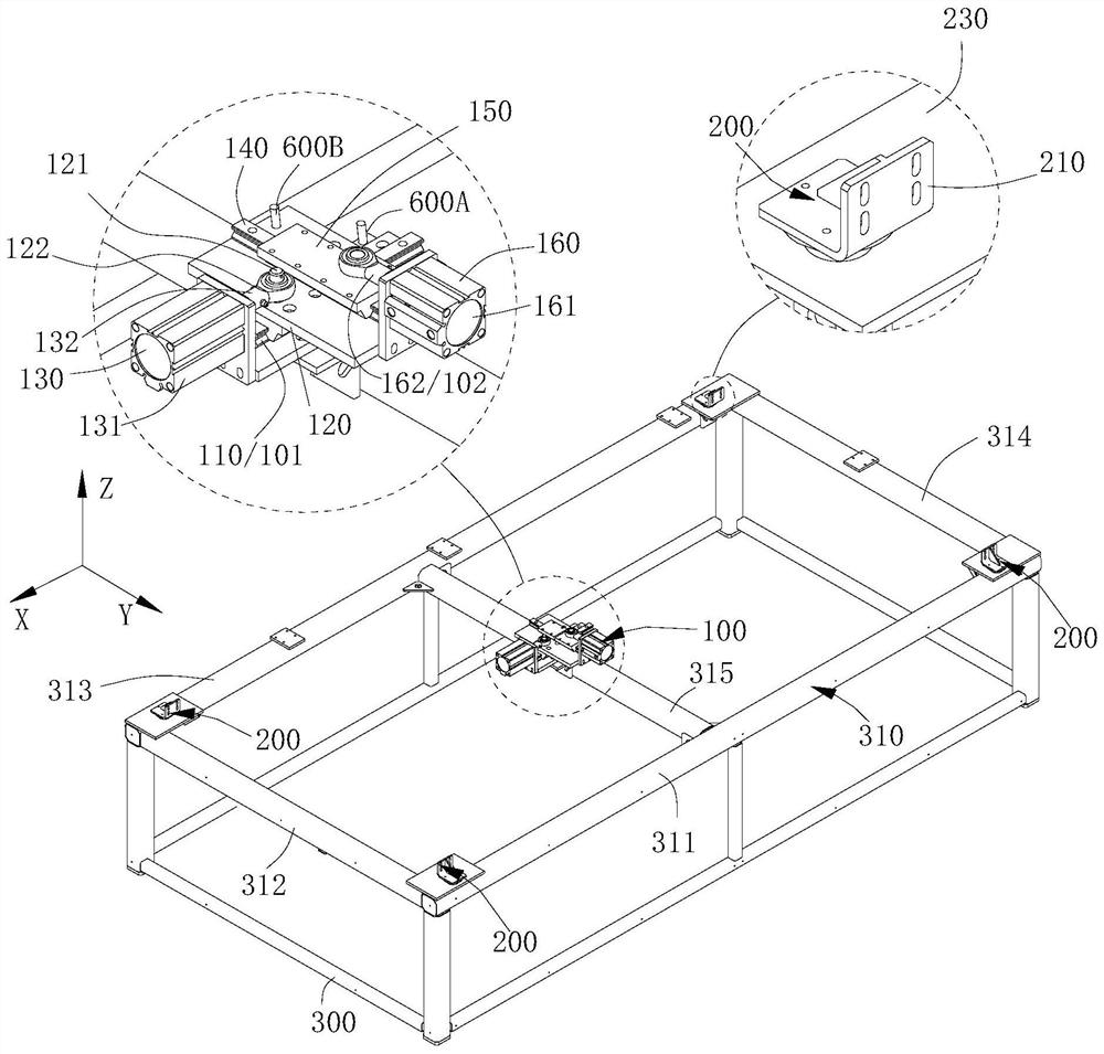
The invention relates to a workpiece correction system, which is used to carry a workpiece and correct the workpiece to a specific position. The workpiece correction system includes: a frame; a drive assembly, including a fixed part and a moving part. The fixed part is fixedly connected to the frame and moves The part is detachably connected to the workpiece, the driving assembly can drag the workpiece to move in a plane along the first direction and the second direction; and the correction assembly is arranged on the frame, and there are at least two correction assemblies. When the drive assembly is dragged When the workpiece moves along one of the directions, the side of the workpiece can hit and stop one of the correcting components, and when the driving component drags the workpiece to move along the other direction, the side of the workpiece can hit and stop another correcting component. Quickly realize the position correction of the workpiece, so that the workpiece can be quickly corrected to the target position, which improves the calibration accuracy, saves labor costs, and improves work efficiency.

Description

technical field [0001] The invention relates to the technical field of mechanical processing auxiliary equipment, in particular to a workpiece correction system. Background technique [0002] Before the plate enters the working area of ​​the bending machine or other plate processing machine tools, due to its heavy weight, the plate needs to be placed on the loading platform with the help of a lifting device. Due to the uncontrollable placement of the operator, the plate may be biased. Moved out of the load platform, thus preventing smooth access to the work area. There are even plates colliding with the machine, causing damage to the machine. [0003] And the thicker plate is heavier, and it is difficult to push it by manpower alone. The current method is to rely on manpower to borrow tools such as crowbars to translate the plate to the effective cutting range of the loading platform, which wastes manpower and material resources and has potential safety hazards. Contents...

Claims


Application Information

Patent Timeline
Patent Type & Authority Patents(China)
IPC IPC(8): B23Q1/25B23Q7/00B21D5/00B21D43/00
CPCB23Q1/25B23Q7/00B21D5/002
Inventor 张衡刘震欧阳韬樊景风赵剑陈焱高云峰
Owner HANS LASER TECH IND GRP CO LTD
Learn More