Special lifting appliance for H-shaped steel beam and lifting method using lifting appliance

A hoisting method, H-shaped steel technology, applied in the direction of transportation and packaging, load hanging components, etc., can solve the problems of long hoisting time, slow installation progress, damage to steel beam paint and steel wire rope, etc., to reduce installation and disassembly time , easy installation and disassembly, and the effect of speeding up the progress of the project

Inactive Publication Date: 2013-04-24
GUANGDONG IND EQUIP INSTALLATION
View PDF6 Cites 3 Cited by
  • Summary
  • Abstract
  • Description
  • Claims
  • Application Information

AI Technical Summary

Problems solved by technology

[0004] The current hoisting method of H-shaped steel beams has the following defects: if the binding is not tight, the steel wire rope may slip, causing hoisting accidents; the position where the steel wire rope contacts the steel beam is not well protected, which will damage the paint and steel wire rope of the steel beam, causing quality and safety problems. Accident; the shackle binding point needs to be adjusted many times, which will make the steel beam in a tilted state after hoisting, causing difficulty in positioning the steel beam; when the steel beam is removed after being in place, the flexible protective material will fall freely, which is difficult to collect during high-altitude hoisting
Therefore, the existing hoisting method hoisting H-shaped steel beams has a large hoisting workload, many hidden dangers to quality and safety, takes up a long time for the hoist, and slow installation progress

Method used


Image

  • Special lifting appliance for H-shaped steel beam and lifting method using lifting appliance
  • Special lifting appliance for H-shaped steel beam and lifting method using lifting appliance
  • Special lifting appliance for H-shaped steel beam and lifting method using lifting appliance

Examples


Embodiment Construction

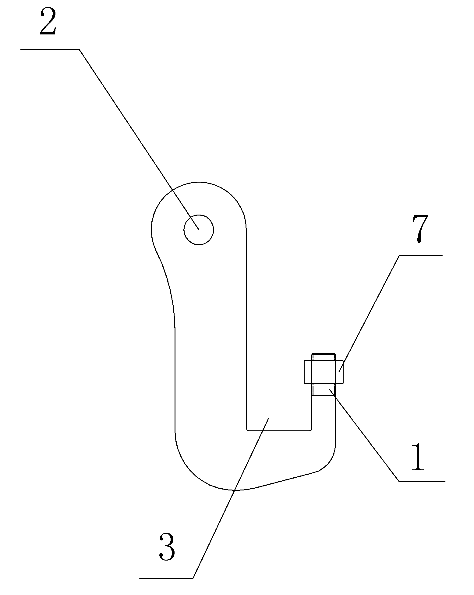
[0018] Such as figure 1 As shown, one of the present embodiments includes a spreader body in the shape of an open groove, one end of the spreader body is provided with a threaded section 1 of M20, the other end is provided with a lifting hole 2, the threaded section 1 of the spreader body and the lifting Between the holes 2 is a tank body 3 for accommodating part of the flange plates of the H-shaped steel beam 4 .

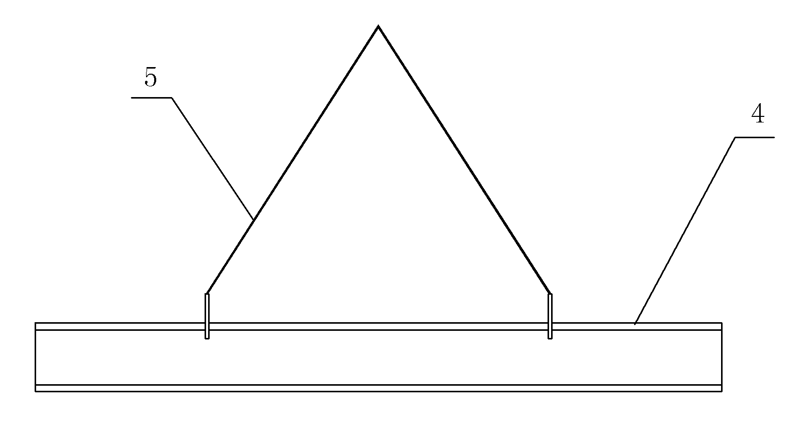
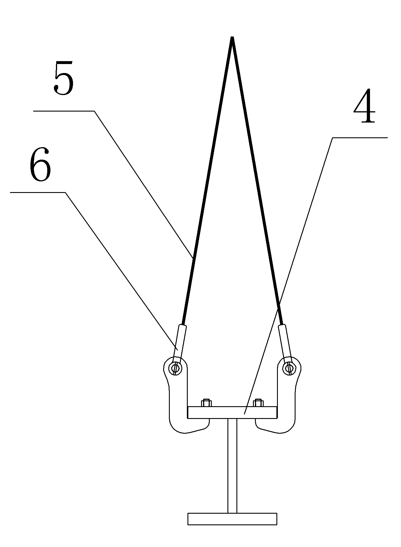
[0019] Such as figure 2 and image 3 As shown, the hoisting method utilizing the above-mentioned H-shaped steel beam 4 special spreaders comprises the following steps:

[0020] a. Open a mounting hole with a diameter of 25mm on the flange of the H-shaped steel beam 4. The mounting hole is symmetrical along the length and width of the upper wing of the H-shaped steel beam 4, and the center line of the mounting hole reaches the flange of the H-shaped steel beam 4. The distance outside the plate is equal to the distance from the center line of threaded section 1 o...


PUM


Abstract

The invention discloses a special lifting appliance for an H-shaped steel beam. The special lifting appliance comprises a lifting appliance body shaped like an open slot, wherein one end of the lifting appliance body is provided with a screw section and the other end is provided with a lifting hole; and a slot body for containing a part of wing plate of the H-shaped steel beam is arranged between the screw section and the lifting hole of the lifting appliance body. The lifting appliance is fixed with the H-shaped steel beam by bolts, thus the lifting appliance is convenient to operate and mount, the mounting point is fixed and is not needed to be adjusted for several times; the fixing effect is good, the slip caused by binding is avoided, and the stable deformation of the H-shaped steel beam is ensured in a lifting process; the lifting appliance is reusable; the H-shaped steel beam is disassembled once the nuts on a mounting rod are released; and the lifting appliance is convenient to mount and demount, the mounting and demounting time of the lifting is greatly reduced, the lifting progress is accelerated, and thus the progress of the overall steel structure engineering is accelerated.

Description

technical field [0001] The invention belongs to the technical field of hanging elements. Background technique [0002] Due to the advantages of light weight, good seismic performance and reusability of steel structures, the proportion of domestic construction steel structures has increased significantly in recent years. In various structures, a large number of H-shaped steel beams are used for floor beams. Most of these steel beams span no more than 8 meters and rarely weigh more than 2 tons. [0003] At present, there is no special spreader for the hoisting of H-shaped steel beams. The current hoisting method of H-shaped steel beams is: use two steel wire rope tails to connect shackles; tie the steel wire ropes with shackles to about a quarter of the span of the steel beam. The four corners where the steel wire rope contacts the steel beam are provided with flexible materials to protect the steel beam and the steel wire rope; before hoisting, adjust the position of the bin...

Claims


Application Information

Patent Timeline
Patent Type & Authority Applications(China)
IPC IPC(8): B66C1/22
Inventor 魏成权张广志王恒陈友明李琦
Owner GUANGDONG IND EQUIP INSTALLATION
Why Eureka
Try Eureka