A method for controlling lubrication of a gear unit and a gear unit

A gear unit, controller technology, applied in the direction of gear lubrication/cooling, belt/chain/gear, thin material handling, etc., to achieve the effect of improving the flow of lubricating fluid

Active Publication Date: 2013-04-24
MOVENTAS GEARS
View PDF7 Cites 5 Cited by
  • Summary
  • Abstract
  • Description
  • Claims
  • Application Information

AI Technical Summary

Problems solved by technology

However, there is always an upper limit to the total lubricating fluid flow, which can easily be reached if an attempt is made to reduce localized high temperatures by increasing the total flow

Method used


Image

  • A method for controlling lubrication of a gear unit and a gear unit
  • A method for controlling lubrication of a gear unit and a gear unit

Examples


Embodiment Construction

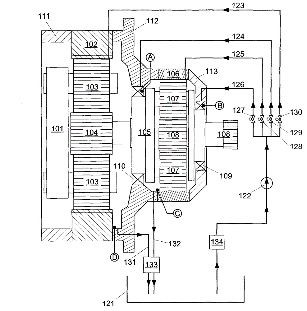
[0024] figure 1 A schematic sectional view of a gear unit according to an advantageous exemplary embodiment of the invention is shown.

[0025] figure 1 The gear unit disclosed in is a planetary gear unit comprising two planetary gear stages. The first planetary gear stage comprises a planet carrier 101 , a ring gear 102 , planet wheels 103 and a sun gear shaft 104 . The second planetary gear stage includes a planet carrier 105 , a ring gear 106 , planet wheels 107 and a sun gear shaft 108 . The planet carrier 101 of the first planetary gear stage forms part of a mechanical interface structure arranged to receive mechanical power from a suitable prime mover. Thus, the planet carrier 101 of the first planetary gear stage is rotated by the prime mover. Ring gear 102 is stationary. The sun gear shaft 104 of the first planetary gear stage is connected to the planet carrier 105 of the second planetary gear stage. Thus, the planet carrier 105 of the second planetary gear stage...


PUM


Abstract

A method for controlling lubrication of a gear unit, in which method temperature of a lubrication fluid circulating in a lubrication channelling of a gear unit is measured, wherein the temperature of lubrication fluid is measured in at least two locations of the gear unit, and larger proportion of the lubrication fluid is directed to the warmer of the at least two locations and correspondingly smaller proportion of the lubrication fluid is directed to the colder of the at least two locations. The invention relates also to such a gear unit.

Description

technical field [0001] The present invention relates to a method for controlling the circulation of lubricating fluid in a gear with one or more controllable valves located in a lubricating oil passage. Background technique [0002] In this specification, we use the term gearwheel to refer to a toothed, rotating piece. Two or more meshing bull gears form a gear stage. Likewise, in this specification the term gear refers to a mechanical system having a first shaft and a second shaft between which one or more gear stages provide a speed in the direction of the axis of rotation and torque shifts and / or changes. The gear unit includes inherent gears and may include auxiliary augmentation systems such as instrumentation, control and lubrication. [0003] Adequate lubrication of the different parts of the gear is very important for the inherent function and life of the gear. In addition to the lubricating effect, the lubricating medium, usually fluid and usually oil, also serv...

Claims


Application Information

Patent Timeline
Patent Type & Authority Applications(China)
IPC IPC(8): F16H57/04
CPCF16H57/0486F16H57/0435F16H57/0413Y10T74/19991Y10T137/0324F16H57/04F16H57/022F16H57/023
Inventor 亚尔诺·胡伊科米科·科波宁萨米·马里斯玛卡里·乌西塔洛
Owner MOVENTAS GEARS
Why Eureka
Try Eureka