Positioning method and electronic device

A technology of electronic equipment and position coordinates, applied in the electronic field, can solve the problems of limited interaction range of electronic equipment, limited shooting angle of image acquisition device, and low positioning ability of electronic equipment, so as to improve interaction ability, improve positioning accuracy, increase The effect of viewing angle range

Active Publication Date: 2013-04-24
HISENSE
View PDF6 Cites 9 Cited by
  • Summary
  • Abstract
  • Description
  • Claims
  • Application Information

AI Technical Summary

Problems solved by technology

[0006] The present invention provides a positioning method and electronic equipment, which are used to solve the problem of limited shooting angle of a single image acquisition device when human-computer interaction is performed t...

Method used


Image

  • Positioning method and electronic device
  • Positioning method and electronic device
  • Positioning method and electronic device

Examples


Embodiment Construction

[0046] The present invention provides a positioning method and device, which are used to solve the problem of the limited shooting angle of a single projection camera when human-computer interaction is performed through a projector in the prior art, which leads to a limited interaction range of electronic equipment and the processing of electronic equipment Capability is also lower on technical issues.

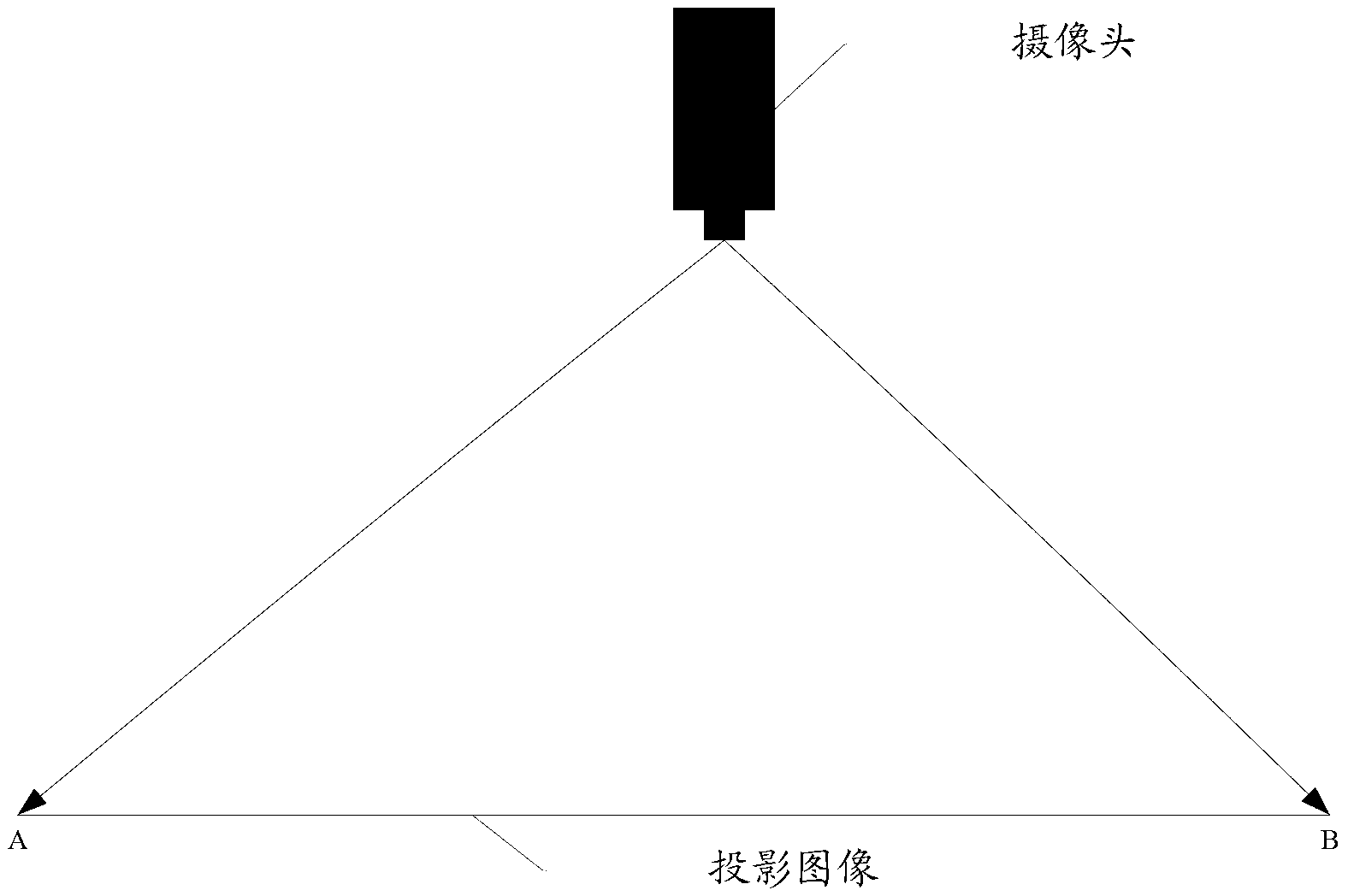
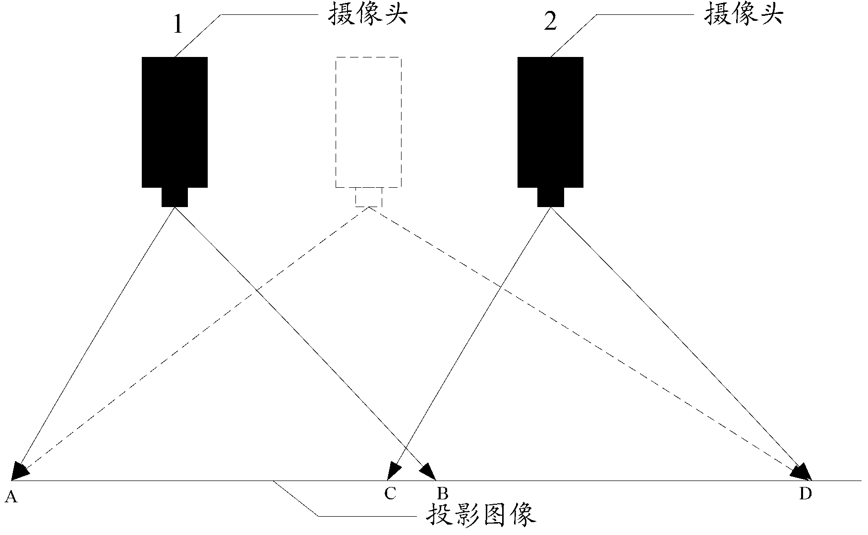
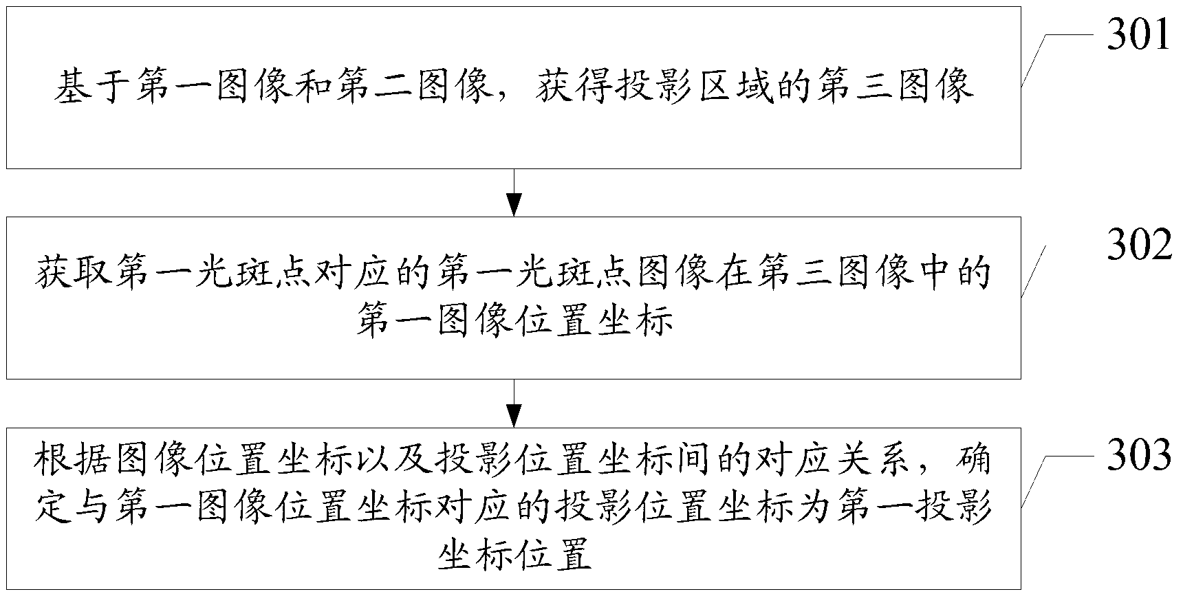
[0047]First of all, it needs to be explained that the projector includes a first image acquisition device, a second image acquisition device and a projection camera, and the projection camera can project the first projection content in the projector on a projection area, and when there is a second When a light spot is projected into the projection area, the first image of the first area in the projection area is collected by the first image acquisition device, and the second image of the second area in the projection area is acquired by the second image acquisition device, Whe...


PUM


Abstract

An embodiment of the invention relates to a positioning method and an electronic device. At least two image acquisition devices are disposed in a projector or an electronic device with a projector to acquire a first image, a second image, and a third image of a projection area. Then first image position coordinates, in the third image, of a first light spot image corresponding to a first light spot are acquired. The projection position coordinates corresponding to the first image position coordinates is determined as first projection position coordinates according to correspondence between the image position coordinates and projection position coordinates. The problem that a singe image acquisition device has limited shooting angle, which leads to limited interaction range of electronic devices, in the prior art is solved. Viewing angle range of projection interactive devices is increased, and interactive capability of projection interactive devices is improved.

Description

technical field [0001] The invention relates to the field of electronic technology, in particular to a positioning method and electronic equipment. Background technique [0002] With the continuous advancement of electronic technology, various human-computer interaction devices have appeared in the prior art. That is to say, the user can use the laser pointer to achieve the control effect of the mouse, so that the user can remotely control the electronic device. [0003] However, the inventor of the present application found that the following technical problems or defects existed in the prior art during the implementation of the present invention: [0004] The projection interaction in the prior art is to collect the image in the projection area through a single image acquisition device set on the projector, then analyze and determine the light spot in the image, and finally determine the position of the light spot. However, the existing In the technology, the shooting an...

Claims


Application Information

Patent Timeline
IPC IPC(8): G06F3/042
Inventor 王震张培龙
Owner HISENSE
Why Eureka
Try Eureka