VPN interconnection method and system

A MP-BGP and routing technology, applied in the field of communication, can solve problems such as network configuration errors, and achieve the effect of reducing network configuration errors

Inactive Publication Date: 2017-10-10
ZTE CORP
View PDF3 Cites 0 Cited by
  • Summary
  • Abstract
  • Description
  • Claims
  • Application Information

AI Technical Summary

Problems solved by technology

[0005] Aiming at the problem in the related art that the first PE and the second PE can only manually configure the parameters of each other, thus easily causing network configuration errors, the present invention is proposed. Therefore, the main purpose of the present invention is to provide a VPN interconnection method and system to solve the above problems

Method used


Image

  • VPN interconnection method and system
  • VPN interconnection method and system
  • VPN interconnection method and system

Examples


Embodiment 1

[0041] This preferred embodiment 1 describes the automatic configuration process of VPN routing information and VRF interface information.

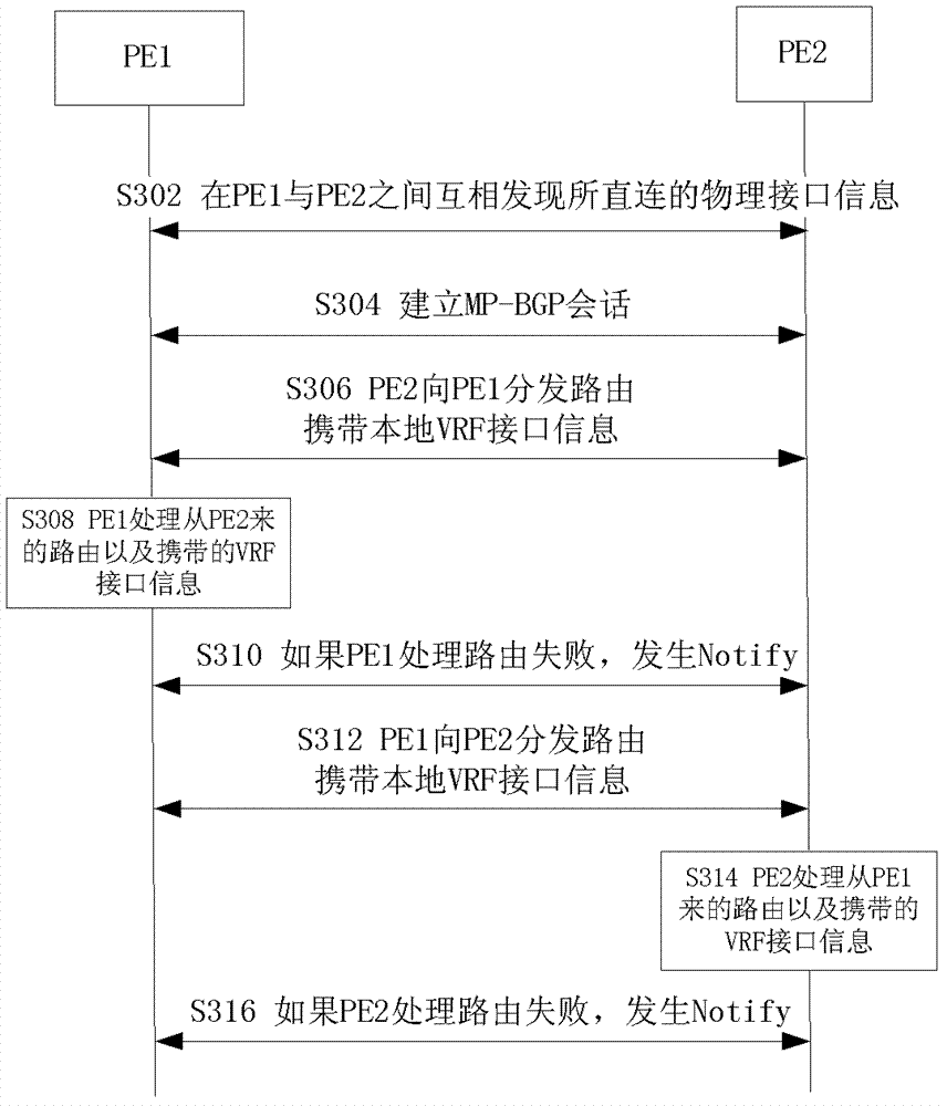
[0042] image 3 It is an interactive flowchart of the VPN interconnection method according to the preferred embodiment 1 of the present invention, such as image 3 As shown, the following steps S302 to S316 are included.

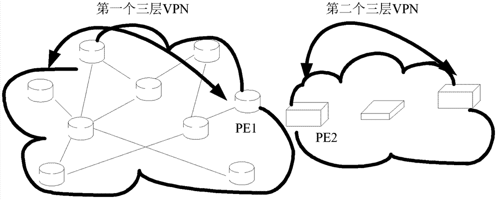
[0043] Step S302 , discover directly connected physical interface parameters between PE1 and PE2 , including system name, port name, and VLAN name. Through the LLDP protocol, static configuration, etc., the mutual direct connection physical interface parameter discovery can be performed. At the same time, you need to configure which of PE1 and PE2 is the active party that initiates the VRF interface configuration.

[0044] Step S304, establishing an MP-BGP signaling channel between PE1 and PE2 for exchanging information between PE1 and PE2, including VPN routing information, VRF interface information, and the like. ...

Embodiment 2

[0052] The second preferred embodiment describes the automatic configuration process of bandwidth information.

[0053] Figure 4 It is an interactive flowchart of the VPN interconnection method according to the second preferred embodiment of the present invention, such as Figure 4 As shown, the following steps S402 to S414 are included.

[0054] Step S402, establishing an MP-BGP signaling channel between PE1 and PE2 for exchanging information between PE1 and PE2.

[0055] Step S404, PE2 distributes routing information to PE1 through MP-BGP signaling, and carries corresponding bandwidth information at the same time. Here, a new MP-BGP route type needs to be defined to carry this routing information; the bandwidth information is the upstream egress bandwidth of this route.

[0056] In step S406, PE1 receives routing information from PE2, generates a corresponding routing entry, and uses the carried bandwidth information as the egress bandwidth of the route.

[0057] Step S...


PUM


Abstract

The invention discloses a VPN interconnection method and system. The method comprises: exchanging VPN routing information and VRF interface information between a first PE and a second PE; generating routing entries corresponding to the VPN routing information respectively by the first PE and the second PE; The first PE and the second PE respectively calculate local VRF interface information matching the VPN routing information; the first PE and the second PE use the local VRF interface information as egress information of the routing entry. The invention can automatically negotiate and configure routing and flow parameters, thereby reducing network configuration errors.

Description

technical field [0001] The present invention relates to the communication field, in particular to a VPN interconnection method and system. Background technique [0002] The Layer 3 VPN based on BGP / MPLS VPN is a full-connection VPN model between PEs. Each PE is connected to the user site network, and a PPVPN (full name: operator-provided VPN) is formed between PEs and PEs. VPN). With the development of VPN network requirements, user site networks are also virtualized into different customer VPNs, so customer VPNs need to be organically connected with PPVPN. Such as figure 1 As shown, the first layer-3 VPN is the layer-3 VPN provided by the WAN, and the second layer-3 VPN is the customer's layer-3 VPN, and these two layer-3 VPNs need to be interconnected. [0003] This application scenario is reflected in the data center VPN service (VPN Data Center Service). With the development of cloud computing, IaaS (that is, the service in which network facilities are leased to user...

Claims


Application Information

Patent Timeline
Patent Type & Authority Patents(China)
IPC IPC(8): H04L12/741H04L12/46H04L12/751H04L45/74H04L45/02
Inventor 金利忠吴波
Owner ZTE CORP
Why Eureka
Try Eureka