
A timing storage rack

A technology for storage racks and timers, applied to electrical components, sensors, etc., can solve problems such as large errors and affect work efficiency, and achieve accurate and reliable timing, improve work efficiency, and be easy to judge

Inactive Publication Date: 2016-12-28
美律电子(惠州)有限公司
View PDF5 Cites 0 Cited by
  • Summary
  • Abstract
  • Description
  • Claims
  • Application Information

AI Technical Summary

Problems solved by technology

Under normal circumstances, using the counting method, the operator needs to check the time after dispensing, which seriously affects the work efficiency and has a large error

Method used


Image

  • A timing storage rack

Examples


Embodiment Construction

[0008] In order to facilitate those skilled in the art to understand the technical content of the present invention, the present invention will be further described in detail below in conjunction with the accompanying drawings and embodiments.

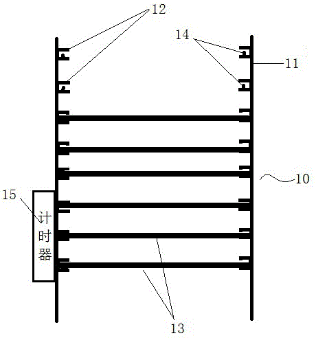
[0009] Such as figure 1 As shown, the timing storage rack shown in this embodiment includes an upright frame body 10, the two symmetrical sides of the upright frame body have baffles 11, and the other two sides are open for the insertion of the load plate. On both side baffles, a card bar 12 is set at a certain distance from top to bottom, for carrying a load plate 13 for carrying items, and an induction switch 14 for inductive load plate loading is arranged in each card bar. The sensor switch is connected with the timer 15 signal.

[0010] When in use, batches of products are directly placed on the carrier plate 13 after dispensing, and the carrier plate 13 is put into the storage rack. At this time, the induction switch 14 is trigge...


PUM


Abstract

The invention relates to a time-keeping storage shelf comprising a vertical shelf body, wherein each of baffles is arranged on each of two symmetrical side faces of the shelf body. Clamping fences in parallel are arranged on each of the two baffles symmetrically. Two sides of bearing board used for bearing articles are respectively arranged, in an erected mode, on the clamping fences. Each of inductive switches used for inducing the erected arrangement of each bearing board is arranged inside each clamping fence. Each of the inductive switches is connected with a timer in a signal mode. Each bearing board is arranged on the clamping fences in an erected mode so as to trigger each inductive switch, the timer receives a signal and controls an indicator light to go on. When the kept time is up, the indicator light goes out. The time-keeping storage shelf is easy to judge for an operator, accurate and reliable in time keeping and capable of improving working efficiency effectively.

Description

technical field [0001] The invention relates to a timing storage rack. Background technique [0002] During the assembly process of the earphone, the speaker and the earphone shell need to be installed together, and glue is applied to stick the two together. It usually takes ten minutes after the glue is applied to make the glue firm, and the bond can only be taken away for the next process. Under normal circumstances, using the counting method, the operator needs to watch the time after dispensing, which seriously affects the work efficiency and has a large error. Contents of the invention [0003] The object of the present invention is to provide a timing storage rack. [0004] The technical solution of the present invention is: a timing storage rack, which is characterized in that it includes an upright frame body with baffles on two symmetrical sides, parallel rails are symmetrically arranged on the two baffles, and the two sides of the carrying plate for carrying ite...

Claims


Application Information

Patent Timeline
Patent Type & Authority Patents(China)
IPC IPC(8): H04R31/00
Inventor 魏文杰
Owner 美律电子(惠州)有限公司
Learn More