
Air conditioning control device, air conditioning control method and program

A control device and air-conditioning technology, which is applied in air-conditioning systems, heating and ventilation control systems, heating methods, etc., can solve the problems of reduced comfort and rising room temperature, and achieve the effect of preventing the reduction of comfort and suppressing the change of air temperature

Active Publication Date: 2013-04-24
MITSUBISHI ELECTRIC CORP
View PDF9 Cites 4 Cited by
  • Summary
  • Abstract
  • Description
  • Claims
  • Application Information

AI Technical Summary

Problems solved by technology

[0002] In a living space where multiple air conditioners are installed, if energy-saving control to suppress power consumption (such as stop control for a certain period of time) is performed simultaneously for all air conditioners, the temperature of the living space may rise sharply and comfort may decrease

Method used


Image

  • Air conditioning control device, air conditioning control method and program
  • Air conditioning control device, air conditioning control method and program
  • Air conditioning control device, air conditioning control method and program

Examples


Embodiment approach 1

[0035] First, Embodiment 1 of the present invention will be described.

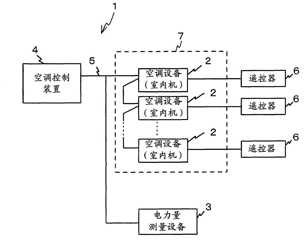
[0036] figure 1 The configuration of the air conditioning system 1 according to Embodiment 1 of the present invention is shown. Such as figure 1 As shown, the air conditioning system 1 of this embodiment includes a plurality of air conditioners (indoor units) 2 , an electric power measurement device 3 , and an air conditioner control device 4 .

[0037] The air conditioner (indoor unit) 2 , the electric power measurement device 3 , and the air conditioner control device 4 are communicably connected to each other by a dedicated communication line 5 . Also, while in figure 1 Not shown in particular, the air-conditioning control device 4 is not only the air conditioner (indoor unit) 2 but also communicably connected to a heat source side unit (outdoor unit) including a compressor and the like via a dedicated communication line 5 . Furthermore, one remote controller (remote controller) 6 is connected to e...

Embodiment approach 2

[0106] Next, Embodiment 2 of the present invention will be described.

[0107] In Embodiment 1 described above, the control unit of the energy-saving control is set as an equipment unit. In this embodiment, a plurality of air conditioners (indoor units) 2 are provided as a group, and an air conditioning system 1 is provided that can perform energy-saving control on a group basis.

[0108] In an actual building or the like, in order to reduce the number of remote controllers 6 , a plurality of air conditioners (indoor units) 2 are often connected to one remote controller 6 as one control unit (one group). Energy saving control by group unit is suitable for such a case.

[0109] If the air conditioners (indoor units) 2 are grouped, in the case of performing energy-saving controls such as stop control and air blowing control that can also be operated by the remote controller 6, it is necessary to control all the air conditioners (indoor units) 2 in the group. Energy-saving cont...


PUM


Abstract

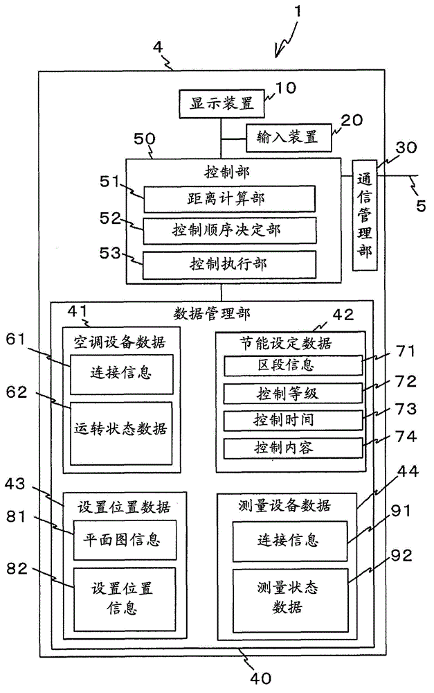
An air conditioning control device (4) controls a plurality of air conditioners (indoor units) installed at different positions of a predetermined room space. A data management unit (40) stores installation position information (82) relating to the respective air conditioners (indoor units). A distance calculation unit (51) calculates the distances between the respective air conditioners (indoor units) on the basis of the installation position information (82). On the basis of the distances between the respective air conditioners (indoor units) calculated by the distance calculation unit (51), a control order determination unit (52) determines the control order of the respective air conditioners (indoor units), on which energy saving control for controlling the respective air conditioners (indoor units) for a predetermined time to reduce power consumption is executed, such that an imbalance in time zone in which the energy saving control is executed is not caused in part of the room space. A control execution unit (53) repeatedly executes the energy saving control of the respective air conditioners (indoor units) in accordance with the control order determined by the control order determination unit (52).

Description

technical field [0001] The present invention relates to an air-conditioning control device, an air-conditioning control method, and a program for controlling a plurality of air-conditioning devices installed at different positions in a living space of a house such as a building. Background technique [0002] In a living space where a plurality of air conditioners are installed, if energy-saving control to suppress power consumption (for example, stop control for a certain period) is performed simultaneously for all the air conditioners, the temperature of the living space may rise sharply and comfort may decrease. [0003] Therefore, a method and a system (for example, Refer to Patent Documents 1 and 2). Accordingly, power saving can be achieved while maintaining a certain level of comfort. [0004] prior art literature [0005] patent documents [0006] Patent Document 1: Japanese Patent No. 4331554 (FIG. 5) [0007] Patent Document 2: Japanese Patent Laid-Open No. 200...

Claims


Application Information

Patent Timeline
IPC IPC(8): F24F11/02
CPCF24F2011/0064F24F2011/0063F24F2011/0075F24F3/065F24F11/006F24F5/00F24F11/0086F24F11/30F24F11/62F24F11/64F24F11/65F24F11/46F24F11/52F24F11/56
Inventor 石阪太一
Owner MITSUBISHI ELECTRIC CORP
Learn More