
A comfortable and energy-saving fresh air fan and its adjustment method

A new fan, fresh air technology, applied in the field of air purification, can solve the problems of uncompact structure, unreasonable layout, large floor space, etc., and achieve the effect of improving space utilization, improving living comfort, and saving energy.

Active Publication Date: 2021-06-15
BROAD A Q TECH
View PDF0 Cites 0 Cited by
  • Summary
  • Abstract
  • Description
  • Claims
  • Application Information

AI Technical Summary

Problems solved by technology

But in winter and summer, even if the outdoor air enters the room through the heat exchanger, it will have a great impact on the indoor temperature, which cannot improve the living comfort.
[0004] Among the existing fresh air fans, there are still multiple independent valves set in different areas to control the flow or blockage of different channels respectively, but this does not solve the problem that the indoor temperature is greatly affected in winter and summer, and multiple independent valves The valves need to be set separately, not only the structure is complicated, but also multiple areas for placing the valves may be set, which takes up a lot of space
[0005] Moreover, the valve linkage mechanism of the existing fresh air blower is located in the chamber, which occupies a large area, and due to unreasonable layout, such as two vertical valves, the overall volume of the fresh air blower is very large, and some are even divided into two parts. A body, resulting in a larger footprint and less compact structure

Method used


Image

  • A comfortable and energy-saving fresh air fan and its adjustment method
  • A comfortable and energy-saving fresh air fan and its adjustment method
  • A comfortable and energy-saving fresh air fan and its adjustment method

Examples


Embodiment Construction

[0032] The invention will be further described in detail below with reference to the accompanying drawings and specific embodiments.

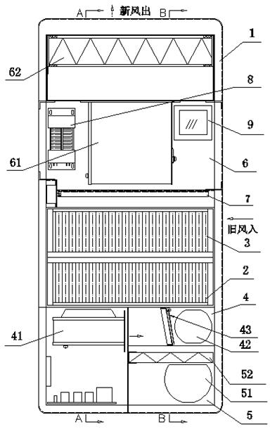
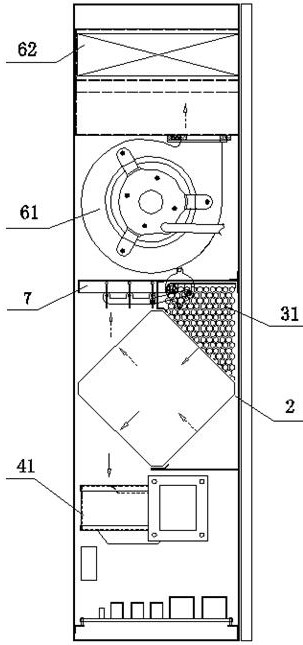
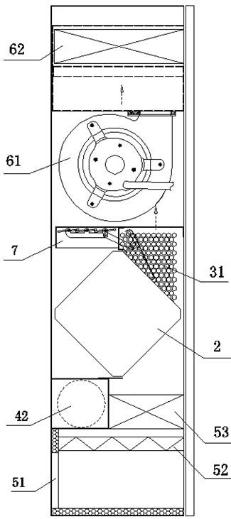
[0033] Such as Figure 1 ~ 6As shown: A comfortable energy-saving new fan, including the casing 1, the old wind exhaust system and a new wind system in the casing, and the heat exchanger is located between the old wind exhaust system and the new wind system; the old The wind exhausting system includes independently set old wind inhalation zones 3 and old wind discharge zones 4; new wind systems include independent set of new wind inhalation zones 5 and new wind discharge zones 6, new wind discharge area 61 with new wind turbine 61 and high efficiency filters 62; The heat exchanger 2, the old wind inhalation region 3 and the new wind discharge area 6 are provided with a valve-linking mechanism, selectively control the valve-linking mechanism according to the outdoor temperature, so that the air in the indoor air is directly discharged from the old wi...


PUM


Abstract

A comfortable and energy-saving fresh air blower and its adjustment method. The comfortable and energy-saving fresh air blower includes a casing, an old air exhaust system and a fresh air system arranged in the casing, and a heat exchange device arranged between the old air exhaust system and the fresh air system. The old air exhaust system includes the old air suction area and the old air discharge area which are set independently; There is a valve linkage mechanism, and the valve linkage mechanism is selectively controlled according to the outdoor temperature, so that the indoor air can only be circulated indoors or double-circulated indoors and outdoors. The invention also includes a method for adjusting a comfortable and energy-saving fresh air blower. On the one hand, the present invention can greatly improve living comfort, has remarkable energy-saving effect, has various operation modes and functions; on the other hand, greatly simplifies the structure and reduces the cost.

Description

Technical field [0001] The present invention relates to the field of air purification technologies, in particular, a comfortable energy-saving fan and its regulation method. Background technique [0002] The existing indoor is generally cleaned by the air in the room, and the new fan can inhale the outdoor new wind in the indoor, and discharge the old wind in the room. Due to the different temperatures in spring and summer, the temperature difference in the summer and winter is large, and the equipment that needs to meet indoor temperature is urgent. [0003] In order to solve the above problems, the existing new fan is usually set up a bypass area. When the summer and winter, the bypass valve of the bypass area is disconnected, the new wind must be refrigerated or heated by the heat exchanger; In the spring and autumn two seasons, the bypass valve is automatically opened, and the new wind in the new air inhalation area directly enters the new wind discharge area after the bypass...

Claims


Application Information

Patent Timeline
Patent Type & Authority Patents(China)
IPC IPC(8): F24F7/08F24F11/84F24F11/89F24F11/64F24F13/30F24F13/28
CPCF24F7/08F24F13/28F24F13/30F24F2221/34F24F11/64F24F11/84F24F11/89
Inventor 张跃
Owner BROAD A Q TECH
Learn More