High-frequency antenna

一种天线、感应天线的技术,应用在天线、环形天线、屏蔽式环形天线等方向,能够解决限制长度等问题

Inactive Publication Date: 2013-04-24
COMMISSARIAT A LENERGIE ATOMIQUE ET AUX ENERGIES ALTERNATIVES
View PDF8 Cites 2 Cited by
  • Summary
  • Abstract
  • Description
  • Claims
  • Application Information

AI Technical Summary

Problems solved by technology

But this structure still has a limited length

Method used


Image

  • High-frequency antenna
  • High-frequency antenna
  • High-frequency antenna

Examples


Embodiment Construction

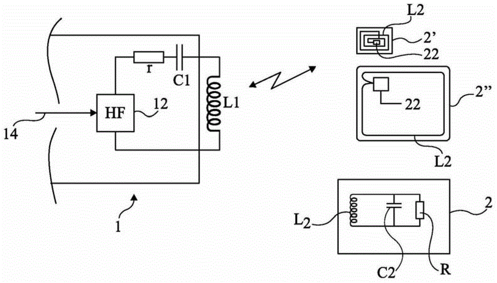
[0049] The same elements are indicated with the same reference numerals in different figures, and the figures are not drawn to scale. For the sake of clarity, only those elements that are useful for understanding the invention are shown and described. In particular, the drive circuit for the inductive antenna is not detailed, the invention being compatible with the drive signals currently used for this type of antenna. In addition, the transponders to which the field generating antennas to be described are directed are not specified, and the present invention is compatible with various current transponders, contactless cards, RFID tags and the like.

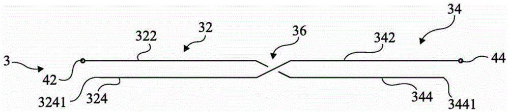
[0050] figure 2 is a simplified view of an antenna according to an embodiment of the invention.

[0051] In this embodiment, multiple coaxial cable sections 32 and 34 are provided for mating. The sections are gathered in pairs 3, and in each pair 3 the two sections 32 and 34 are connected in a Moebius-type connection, that is, ...


PUM


Abstract

The invention relates to an inductive antenna formed from at least two pairs of segments (32, 34) geometrically butted together and each comprising first (322, 342) and second (324, 344) parallel conductors insulated from each other, each pair having, at each end, a single terminal for the electrical connection of its first conductor to that of the neighbouring pair, in which said pairs are of a first type (3), in which the conductors are interrupted approximately at their mid-points so as to define the two segments, the first (respectively second) conductor of one segment being connected to the second (respectively first) conductor of the other segment of the pair, or of a second type, in which the first conductor is interrupted approximately at its mid-point so as to define the two segments, the second conductor not being interrupted.

Description

technical field [0001] The present invention relates generally to antennas, and more particularly to the formation of high frequency induction antennas. [0002] The invention applies more particularly to antennas intended for radio frequency transmission of a few MHz, for example antennas for contactless chip cards, RFID tags, or electromagnetic transponder transmission systems. Background technique [0003] figure 1 An example of a type of inductive transmission system to which the invention applies as an example is shown very schematically. [0004] Such systems include a reader or base station 1 that generates an electromagnetic field that can be detected by one or more transponders 2 located in the field. Such a transponder 2 is, for example, an electronic tag 2' placed on an object for identification purposes, a contactless smart card 2'', or more generally any electromagnetic transponder (using figure 1 Indicated by square 2 in ). [0005] On the reader 1 side, a ...

Claims


Application Information

Patent Timeline
Patent Type & Authority Applications(China)
IPC IPC(8): H01Q7/00H01Q7/04H01Q21/10
CPCH01Q7/04H01Q21/10H01Q7/00
Inventor 蒂埃里·托马斯
Owner COMMISSARIAT A LENERGIE ATOMIQUE ET AUX ENERGIES ALTERNATIVES
Why Eureka
Try Eureka