Polishing pad for a polishing system

A polishing pad and polishing liquid technology, applied in the field of polishing pads, can solve the problems of slippage in the polishing process, high polishing rate, large amount of polishing liquid, etc., and achieve the effect of uniform and wide process range

Active Publication Date: 2013-05-01
LG CHEM LTD
View PDF7 Cites 4 Cited by
  • Summary
  • Abstract
  • Description
  • Claims
  • Application Information

AI Technical Summary

Problems solved by technology

This results in a flow difference or non-uniform flow of the polishing fluid flowing through the grooves formed at the polishing pad 1
Meanwhile, in the case where the pol

Method used


Image

  • Polishing pad for a polishing system
  • Polishing pad for a polishing system
  • Polishing pad for a polishing system

Examples


Embodiment Construction

[0042] The words used in the following detailed description are for the sake of convenience and should not be used to limit the present disclosure. Words such as "left", "right", "top", and "bottom" denote different directions referred to in the drawings. Words such as "inwardly" and "outwardly" denote directions towards and away from, respectively, the geometric center of the respective designed instrument. Words such as "front", "rear", "above", "below" and their related words and phrases indicate the position and orientation of references in the drawings and they are not intended to limit the present disclosure. These words include those listed above, their derivatives, and their synonyms.

[0043] Exemplary embodiments will be described with reference to the drawings.

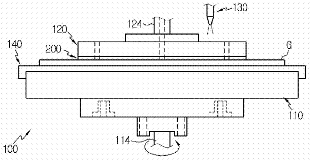
[0044] image 3 is a schematic diagram illustrating a glass plate polishing system in which a polishing pad according to a preferred embodiment of the present disclosure may be installed.

[0045] refer t...


PUM


Abstract

A polishing pad of a polishing system is mountable to a polishing plate and has a predetermined channel pattern so as to allow a polishing liquid supplied from a polishing liquid supplier to move on a polishing surface. The channel pattern has at least two kinds of patterns.

Description

technical field [0001] The present disclosure relates to a polishing pad, and more particularly, to a polishing pad of a polishing system for polishing a glass plate for a liquid crystal display. Background technique [0002] In general, it is very important to maintain the flatness of a glass plate (or glass substrate) for a liquid crystal display to a specified level in order to accurately represent an image. The glass sheets are produced by the fusion method or the float method. Most existing glass sheets (approximately 95% or more) are produced by the float process. Float-produced glass (or float glass) is processed into ribbons in floating basins and cut into predetermined dimensions in a subsequent cutting process. In addition, a polishing process is performed to remove fine unevenness or impurities appearing on the surface of the float glass. [0003] Meanwhile, the polishing process of the glass substrates may be classified into a method of polishing individual gl...

Claims


Application Information

Patent Timeline
IPC IPC(8): B24D11/00B24D7/00B24B7/00
CPCB24B37/245B24B37/26
Inventor 闵庚勳林云勳李大渊宋在翊朴寿讃
Owner LG CHEM LTD
Why Eureka
Try Eureka