Semiconductor substrate, method for fabricating the same, and method for fabricating semiconductor device

a semiconductor device and substrate technology, applied in the field of semiconductor device manufacturing, can solve the problems of inability to achieve the above-mentioned objective value, inability to use conventional cmp technology, size variation or inter-electrode short circuit, etc., to achieve the effect of stabilizing the polishing speed, reducing the polishing speed, and increasing the polishing speed of the locus portion of the polishing pad

Inactive Publication Date: 2006-09-05
PANASONIC CORP
View PDF21 Cites 15 Cited by
  • Summary
  • Abstract
  • Description
  • Claims
  • Application Information

AI Technical Summary

Benefits of technology

[0013]Specifically, CMP is performed by rotating each of a polishing pad affixed to a platen and a semiconductor wafer, while simultaneously pressing the semiconductor substrate against the polishing pad. Since the semiconductor substrate is pressed against the polishing pad under a load of about 1 N / cm2 or more, pores in urethane foam composing the polishing pad are crushed so that an abrasive is not supplied evenly to the entire surface of the semiconductor wafer and the polishing speed is thereby reduced. To prevent this, measures have been taken which uniformly move a dresser (not shown) having diamond mounted in fixed relation thereon over the polishing pad to roughen the surface of the polishing pad and thereby stabilize the polishing speed.
[0014]However, each of the shoulder portions of the notch provided in the semiconductor wafer has the effect of roughening the surface of the polishing pad, not the effect of crushing the polishing pad, since it functions as a singularity point which perpendicularly hits on the polishing pad during polishing. As a result, the surface portion of the polishing pad corresponding to the locus of the notch along which the notch has moved during, e.g., STI-CMP is roughened, which causes the possibility that the polishing speed of the locus portion of the polishing pad is increased unintentionally. At present, the setting of the speed of rotation of, e.g., the semiconductor wafer or the polishing pad and the like is performed such that an arbitrary point on the semiconductor wafer follows a random locus on the polishing pad during polishing. However, since the semiconductor wafer is not fixed completely to the head (not shown) of the polishing machine, it is difficult to render the locus on the polishing pad followed by an arbitrary point on the semiconductor wafer as random as calculated so that the same locus occurs at each constant speed of rotation.

Problems solved by technology

However, the uniformity of an amount of grinding of the nitride film (the ratio of an error to an objective amount of grinding) cannot be suppressed to 5% or less at the foregoing peripheral edge portion of the wafer (especially in a range of the peripheral edge portion extending radially about 2 to 5 mm from the edge surface of the wafer) and hence the foregoing objective value cannot be achieved.
However, the objective value cannot be achieved by using the conventional CMP technology including the semiconductor wafer, the end-point detection film (such as the nitride film), and the end-point detection method which are used currently in combination.
In this case, variations in the final thickness of the end-point detection film eventually lead to steps produced on the isolation region and steps produced on the active region to be formed with a semiconductor element so that a problem such as size variations or an inter-electrode short circuit occurs during the formation of, e.g., the gate electrode of a MOS transistor.

Method used


Image

  • Semiconductor substrate, method for fabricating the same, and method for fabricating semiconductor device
  • Semiconductor substrate, method for fabricating the same, and method for fabricating semiconductor device
  • Semiconductor substrate, method for fabricating the same, and method for fabricating semiconductor device

Examples


embodiment 1

[0055]A semiconductor substrate and a fabrication method therefor according to the first embodiment of the present invention will be described herein below with reference to the drawings.

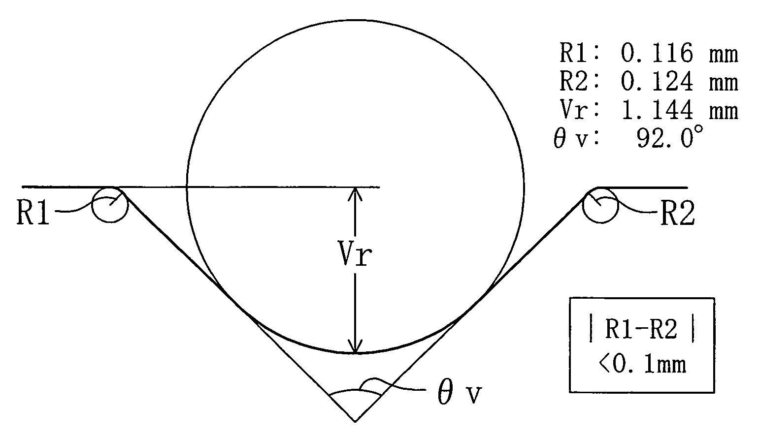
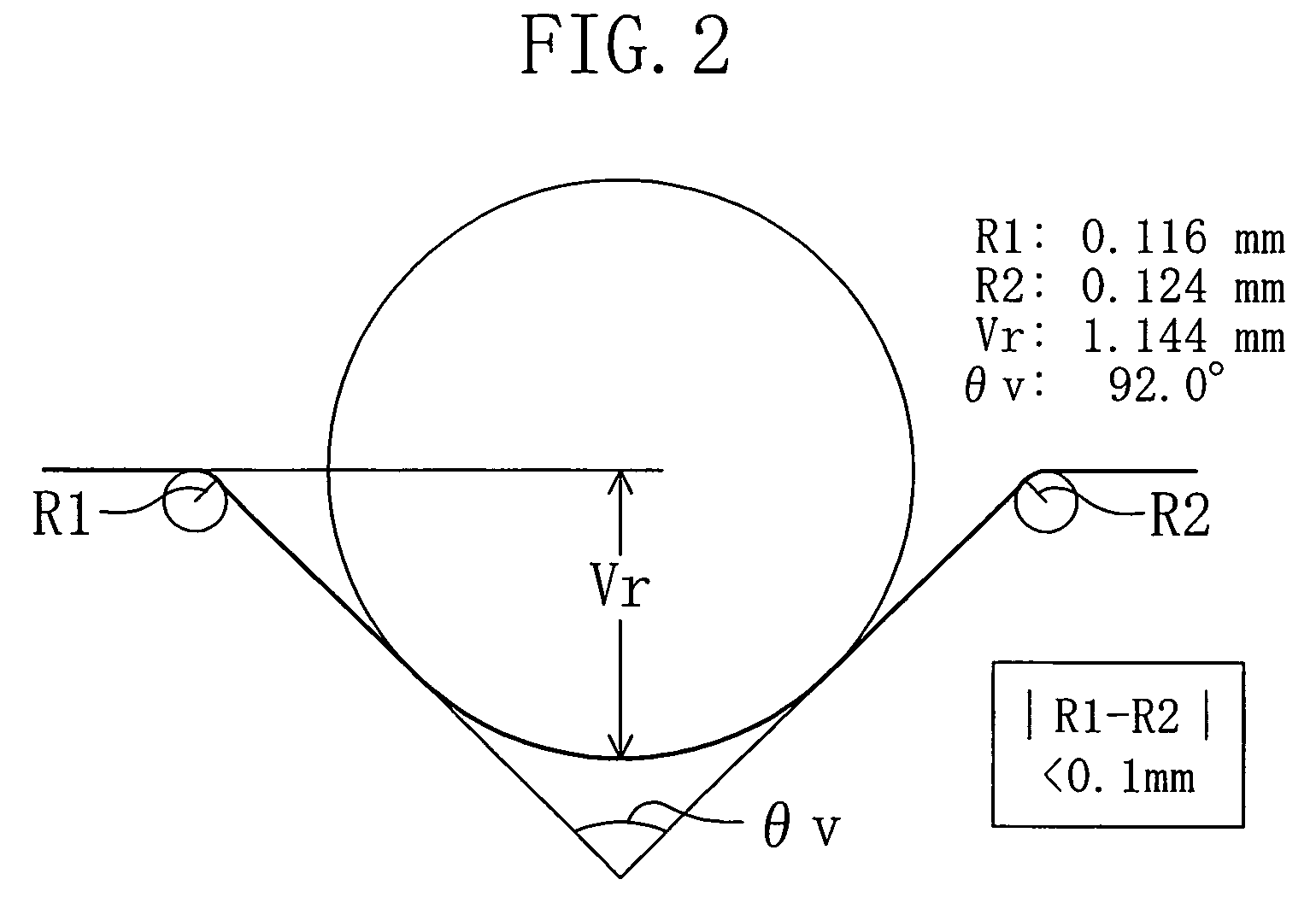
[0056]The semiconductor substrate according to the first embodiment is characterized in that each of the two shoulder portions of a notch formed in an edge portion thereof has an arcuate configuration and the difference in curvature between the two shoulder portions is not less than 0 mm and not more than 0.1 mm. In other words, the two shoulder portions of the notch in the semiconductor substrate (semiconductor wafer) according to the first embodiment have equal configurations. This prevents the production of steps on the surface of the semiconductor wafer after, e.g., STI-CMP, specifically a reduction in the final thickness of a polished film at the peripheral edge portion of the wafer after STI-CMP.

[0057]FIG. 2 shows an exemplary configuration of the notch in the semiconductor substrate according...

embodiment 2

[0074]A semiconductor substrate and a fabrication method therefor according to the second embodiment of the present invention will be described with reference to the drawings.

[0075]A first feature of the semiconductor substrate according to the second embodiment is that each of the two shoulder portions of a notch formed in an edge portion thereof has an arcuate configuration and the difference in curvature between the two shoulder portions is not less than 0 mm and not more than 0.1 mm, in the same manner as in the first embodiment. A second feature of the semiconductor substrate according to the second embodiment is that the curvature of each of the shoulder portions of the notch is 0.3 mm or more. In other words, the two shoulder portions of the notch have equal configurations in the semiconductor substrate (semiconductor wafer) according to the second embodiment and, in addition, the curvature of each of the two shoulder portions of the notch is larger in the second embodiment t...

embodiment 3

[0096]Referring to the drawings, a method for fabricating a semiconductor device according to a third embodiment of the present invention, specifically a method for fabricating a semiconductor device using the semiconductor substrate (semiconductor substrate characterized by the configurations of the shoulder portions of the notch) according to the first or second embodiment will be described herein below.

[0097]FIGS. 12A to 12C are cross-sectional views illustrating the individual process steps of the method for fabricating a semiconductor device according to the third embodiment.

[0098]First, as shown in FIG. 12A, a protective oxide film (SiO2 film) 102 and a nitride film (SiN film) 103 serving as an end-point detection film for STI-CMP are formed successively on a semiconductor substrate 101. A notch with two shoulder portions having a curvature difference not less than 0 mm and not more than 0.1 mm therebetween is provided in the edge portion of the semiconductor substrate 101. Pr...


PUM

PropertyMeasurementUnit
angleaaaaaaaaaa
angleaaaaaaaaaa
thicknessaaaaaaaaaa

Abstract

In a semiconductor substrate having a notch in an edge portion thereof, each of the two shoulder portions of the notch is configured as an arc and the difference in curvature between the two shoulder portions of the notch is not less than 0 mm and not more than 0.1 mm.

Description

BACKGROUND OF THE INVENTION[0001]The present invention relates to a semiconductor substrate, a method for fabricating the same, and a method for fabricating a semiconductor device.[0002]The recent rapid advancement of miniaturization technology has achieved an exponential increase in the number of semiconductor elements in a semiconductor device, i.e., a higher degree of integration. Accordingly, active regions to be formed with semiconductor elements and isolation regions between the semiconductor elements have been reduced in size significantly. As a result, STI (Shallow Trench Isolation) which buries an oxide insulating film in fine trenches provided in a substrate has been used as a replacement isolation method for LOCOS isolation involving an oxidation process.[0003]A specific method for forming the STI is as follows. First, isolation trenches are formed in a substrate and then an oxide insulating film is buried in each of the isolation trenches by CVD (Chemical Vapor Depositio...

Claims


Application Information

Patent Timeline
Patent Type & Authority Patents(United States)
IPC IPC(8): H01L29/06H01L21/304H01L21/306H01L21/762H01L23/544
CPCH01L21/02008H01L23/544H01L21/76224H01L21/02024H01L2223/54493H01L2924/0002H01L2924/00A47G33/02B44C5/0407E04H13/001E04H13/008
Inventor HIDAKA, YOSHIHARUIKENOUCHI, KATSUYUKI
Owner PANASONIC CORP
Why Eureka
Try Eureka