Lifting chair

A seat and seat surface technology, applied in the field of lift seats, can solve the problem that the lift seats cannot be disassembled, packaged and transported, and achieve the effects of simple and stable structure, convenient installation, convenient packaging and use

Inactive Publication Date: 2013-05-08
李波
View PDF0 Cites 1 Cited by
  • Summary
  • Abstract
  • Description
  • Claims
  • Application Information

AI Technical Summary

Problems solved by technology

[0003] In order to overcome the disadvantage that the lift seat cannot be disassembled and is not convenient for packaging and transportation, the present invention provides a detachable lift seat. The seat is made of a seat surface, a seat surface base, chair legs, and a backrest. On the base of the chair surface, there are fixing tubes on the base of the chair surface for installing the chair legs and the backrest, and the chair legs and the backrest can be inserted into the fixing tubes; there are fixing holes on the fixing tubes for fixing the chair legs and the backrest

Method used


Image

  • Lifting chair
  • Lifting chair
  • Lifting chair

Examples


Embodiment Construction

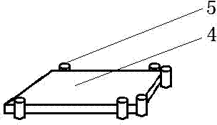
[0011] Such as figure 1 Shown: Use wood or plastic for the seat surface.

[0012] Such as image 3 Shown: Metal materials are used to weld the seat base.

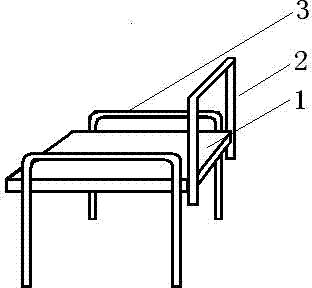
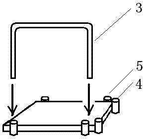
[0013] Such as image 3 Shown: use metal material welding or hot bending, cold bending to make chair legs and backrest.

[0014] Such as Figure 4 Shown: Drill holes for the seat base fixing pipe, chair legs and backrest.

[0015] Installation before sales: the chair surface and the chair surface base are fixed together, and the chair legs and backrest are not fixed on the chair surface base, and are directly packaged.

[0016] Installation during use: insert the chair legs and backrest into the fixing tube on the seat base, adjust the height and fix them, and the installation is completed.


PUM


Abstract

A dismountable lifting chair is composed of a chair face, a chair face base, chair legs, and a backrest. The chair face is fixed on the chair face base. The chair face base is provided with chair legs and a fixed tube. The chair legs and the backrest can slide in the chair face base fixed tube to achieve seat height adjustment.

Description

technical field [0001] The invention relates to a seat, in particular to a detachable lifting seat. Background technique [0002] The height of children will continue to increase with age, and using lifting desks and chairs is an effective way to solve this problem. Existing liftable desks and seats are all sold as finished products, have relatively large volume and weight, are not convenient for packaging and selling, and are not convenient for buyers to carry and transport. Contents of the invention [0003] In order to overcome the disadvantage that the lift seat cannot be disassembled and is not convenient for packaging and transportation, the present invention provides a detachable lift seat. The seat is made of a seat surface, a seat surface base, chair legs, and a backrest. On the base of the seat surface, there are fixing tubes for installing the legs and the backrest on the base of the chair surface, and the legs and the backrest can be inserted into the fixing t...

Claims


Application Information

Patent Timeline
Patent Type & Authority Applications(China)
IPC IPC(8): A47C4/02A47C3/20A47C7/40A47C7/02A47B91/00
Inventor 李波
Owner 李波
Why Eureka
Try Eureka