Valve plate of feed bin discharge valve

A technology of unloading valve and valve plate, which is applied in the field of valve spare parts, can solve the problems of easily damaged silo, reduce the service life of the machine, waste manpower, etc., and achieve the effects of low manufacturing cost, increased service life and simple structure

Inactive Publication Date: 2013-05-08
SUZHOU DONGLI MACHINERY
View PDF0 Cites 5 Cited by
  • Summary
  • Abstract
  • Description
  • Claims
  • Application Information

AI Technical Summary

Problems solved by technology

However, manual guarding is a waste of manpower, and it cannot guarantee that the blocking phenomenon will be solved in time; installing a vibrating device will increase the cost of the manufacturer
In addition, t

Method used


Image

  • Valve plate of feed bin discharge valve

Examples


Embodiment Construction

[0011] The present invention is described below in conjunction with accompanying drawing.

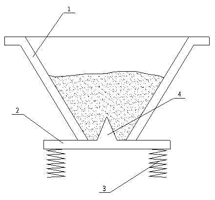
[0012] attached figure 1 It is a valve plate of a silo discharge valve according to the present invention, including a valve plate 2 fixed inside the valve body (not shown in the figure); the valve plate 2 is located at the bottom of the silo 1, and the valve plate 2 Fixed in the valve body by a spring 3; the valve plate 2 is located at the center of the bin 1 and is provided with a conical projection 4; the cone angle of the conical projection 4 is 24°; the conical The height of the bump 4 is at least 1 / 6 of the height of the feed bin 1 .

[0013] Due to the application of the above-mentioned technical solution, the present invention has the following advantages compared with the prior art:

[0014] The valve plate of the silo discharge valve of the present invention can automatically solve the material blocking phenomenon in the silo without shaking the silo, has simple structure, l...


PUM

PropertyMeasurementUnit
Cone angleaaaaaaaaaa

Abstract

The invention discloses a valve plate of a feed bin discharge valve. The valve plate comprises a valve plate body which is fixed inside a valve body through a spring and positioned at the bottom of a feed bin, a conical projection with a cone angle of 24 degrees is arranged at a position, at the center of a feed bin opening, on the valve plate body, and the height of the conical projection is one-sixth of that of the feed bin. The valve plate of the feed bin discharge valve in the scheme is capable of automatically solving the problem of material blockage in the feed bin without shaking the feed bin, and is simple in structure, low in manufacturing cost and capable of effectively prolonging service life of a machine.

Description

technical field [0001] The invention relates to a valve plate installed in a valve, in particular to a valve plate of a discharge valve on a silo, and belongs to the technical field of valve spare parts. Background technique [0002] In many silos for industrial production, a discharge valve is installed to control the material in the silo. In order to ensure normal unloading, the silos are designed as inverted cones, and the unloading valve is installed at the bottom of the silo, and the material in the silo is released by opening and closing the valve plate and valve body in the unloading valve. At present, there are many automatic control methods for the unloading valve, such as electric, pneumatic, spring control, etc., but in some small production enterprises, in order to save costs, the spring control method is generally used, that is, through the gravity of the material. The spring pushes open the valve plate to realize unloading; when the unloading is completed, the...

Claims


Application Information

Patent Timeline
IPC IPC(8): F16K1/36B65D88/64
Inventor 叶晓峰
Owner SUZHOU DONGLI MACHINERY
Why Eureka
Try Eureka