Multi-energy combination hot water system and multi-energy control switching method

A technology of hot water system and control method, which is applied in the direction of residential hot water supply system, heating system, renewable energy integration, etc., which can solve the problems of inconvenient use and high energy consumption, and achieve cost reduction, convenient maintenance, and convenient replacement Effect

Active Publication Date: 2013-05-08
HAIER GRP CORP +1
View PDF7 Cites 15 Cited by
  • Summary
  • Abstract
  • Description
  • Claims
  • Application Information

AI Technical Summary

Problems solved by technology

[0005] In order to solve the existing combination of solar water heaters and other energy sources, the advantages and disadvantages of which have not been fully considered. Therefore, there are problems such as large energy consumption, inconvenient use, and heat exchange efficiency after the combination. A multi-energy combination hot water system is proposed, which adopts the following technology Program:

Method used


Image

  • Multi-energy combination hot water system and multi-energy control switching method
  • Multi-energy combination hot water system and multi-energy control switching method
  • Multi-energy combination hot water system and multi-energy control switching method

Examples


Embodiment 1

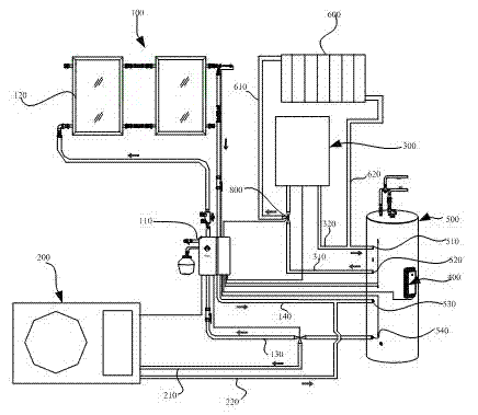
[0037] Embodiment one, refer to figure 1 , this implements a multi-energy combination hot water system, which uses an integrated method to realize the matching and switching of four energy sources: solar energy, air source heat pump, gas, and auxiliary electricity, so as to achieve the lowest energy consumption and the best energy-saving effect, which is conducive to energy conservation and emission reduction The implementation is as follows: it includes a solar heating unit, a heat pump heating unit, a gas heating unit, an electric heating unit and a water storage tank.

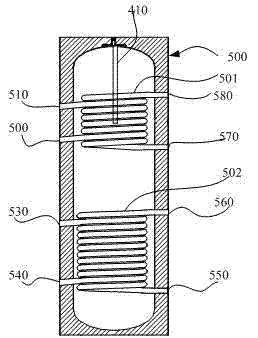
[0038] The water storage tank 500 is installed with a temperature sensor (not shown in the figure) and two sets of upper and lower heat exchangers 501, 502. Each set of heat exchangers includes two coils, and the upper and lower cold water tanks are opened on the tank. Inlets 570, 550, upper and lower hot water outlets 580, 560, upper and lower heat collection cycle inlets 510, 530, upper and lower heat coll...

Embodiment 2

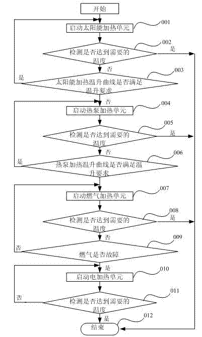
[0045] Embodiment two, refer to figure 2 , this embodiment proposes a multi-energy control switching method on the basis of Embodiment 1, and the conditions for stopping and starting each energy source in this embodiment are performed in the following order:

[0046] 1. Solar heating: As long as the starting conditions of the solar heat collection cycle are met, the circulating pump in the solar pumping station will start;

[0047] 2. Heat pump heating: Under the condition of selecting the heat pump, consider that the heat pump has priority over electric heating, and control the heat pump heating through the system controller according to the temperature in the water storage tank.

[0048] 3. Gas heating: When the heat pump and solar energy cannot meet the requirements, the temperature in the water storage tank is detected, and the gas heating is performed under the control of the system controller.

[0049] 4. Electric heating: When solar energy, heat pump, or gas heating c...


PUM


Abstract

The invention provides a multi-energy combination hot water system and a multi-energy control switching method. According to the multi-energy combination hot water system, when a water heater is used by a large number of users, solar energy, a heat pump, gas and electric heating are started sequentially by a system controller, so that comfortable water experience is provided for the users quickly to achieve an optimum energy-saving effect; each heating unit is an independent heating unit; the modular design of the heating units is adopted, interfaces are unified, and later-period maintenance and replacement are convenient, so that the cost is reduced; and a gas heater and an electric heater are arranged on the upper side, so that hot water can be provided quickly when external environment is poor.

Description

technical field [0001] The invention belongs to the technical field of solar water heaters, and in particular relates to a multi-energy hot water system combined with solar energy, heat pump, gas and electric heating, and a control switching mode of the multi-energy system. Background technique [0002] As a green and environmental protection product, solar water heaters have been widely accepted and formed a huge development market. In small and medium-sized cities and vast rural areas, more and more families use solar water heaters to provide domestic hot water. [0003] However, in rainy weather, the solar water heater cannot provide hot water, and this situation brings great inconvenience to users. In order to solve the above problems, existing methods of adding auxiliary energy to solar water heaters are proposed, which mainly include the following methods: 1. Combination of solar energy and electric heating, electric heating is not limited by other environmental factor...

Claims


Application Information

Patent Timeline
IPC IPC(8): F24D17/00F24D19/10
CPCY02B10/20Y02B10/70
Inventor 杨春涛渠荣华王少鹏
Owner HAIER GRP CORP
Why Eureka
Try Eureka