Measuring method and system of electronic tag matching impedance

A technology of electronic tags and matching impedance, which is applied in the field of measurement, can solve the problems of wasting time, cost, and antenna materials, and achieve the effects of improving design accuracy, simplifying antenna design, and saving design time and cost

Active Publication Date: 2013-05-08
NATIONZ TECH INC
View PDF6 Cites 9 Cited by
  • Summary
  • Abstract
  • Description
  • Claims
  • Application Information

AI Technical Summary

Problems solved by technology

In the prior art, there is no antenna design by obtaining the precise impedance of the electronic tag chip at the limit of sensitivity, but by making dozens or even hundreds of antennas with different impedances to find a suitable antenna. The problem is that it needs to go through a lot of tests and consume a lot of antenna materials, which also wastes a lot of time, and it takes the above work when designing the antenna for the next application

Method used


Image

  • Measuring method and system of electronic tag matching impedance
  • Measuring method and system of electronic tag matching impedance
  • Measuring method and system of electronic tag matching impedance

Examples


Embodiment Construction

[0032] The principles and features of the present invention are described below in conjunction with the accompanying drawings, and the examples given are only used to explain the present invention, and are not intended to limit the scope of the present invention.

[0033] Here, a specific embodiment is used to illustrate the method for measuring the matching impedance of the electronic tag of the present invention. In this embodiment, the method for measuring the matching impedance of the electronic tag may include the following steps:

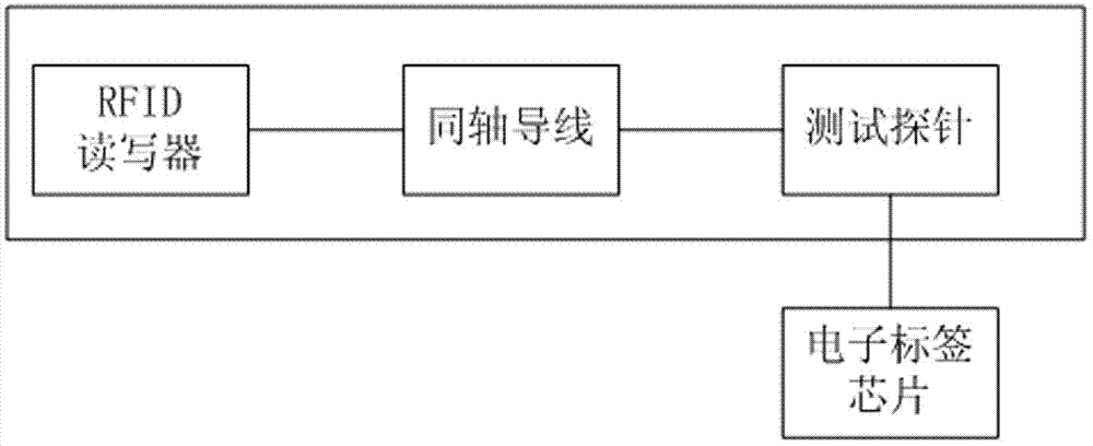
[0034] The first step is to connect the reader, coaxial wire, test probe, and electronic tag chip in sequence to find the minimum allowable output power P0 of the reader;

[0035] The minimum allowable output power P0 refers to the minimum output power of the reader-writer that can support the work of the electronic tag chip.

[0036] In the first step, the coaxial wires and test probes are not calibrated.

[0037] figure 1 It is a schemati...


PUM


Abstract

The invention relates to a measuring method and a system of electronic tag matching impedance. The measuring method of the electronic tag matching impedance comprises the steps of connecting a reader-writer, a coaxial wire, a test probe and an electric tag chip in sequence, finding out the minimum output power P0 that the reader-writer can support the electric tag chip to work, connecting a vector network analyzer, the calibrated coaxial wire, the corrected test probe and the electric tag chip in sequence, setting output power of the vector network analyzer to be the P0, obtaining a fourth echo reflected value through measurement, processing the fourth echo reflected value, and obtaining the matching impedance of the electric tag chip. According to the measuring method and the system of the electronic tag matching impedance, a resistance value of the electric tag chip in a sensitivity limit can be obtained, and therefore the antenna design of an electric tag is simplified, design time and cost are saved, and design precision is improved.

Description

technical field [0001] The invention relates to the field of measurement, in particular to a method and system for measuring matching impedance of an electronic tag. Background technique [0002] RFID (Radio Frequency Identification, Radio Frequency Identification) is a non-contact automatic identification technology. It automatically identifies the target object and obtains relevant data through radio frequency signals. The identification work does not require manual intervention and can work in various harsh environments. RFID can identify high-speed moving objects and can identify multiple electronic tags at the same time, and the operation is fast and convenient. [0003] The RFID system is a simple wireless system with only two basic components, which is used to control, detect and track objects. [0004] RFID systems are divided into low-frequency LF, high-frequency HF, ultra-high-frequency UHF, and microwave MW according to different operating frequencies in specific...

Claims


Application Information

Patent Timeline
Patent Type & Authority Applications(China)
IPC IPC(8): G01R27/02
Inventor 甘泉
Owner NATIONZ TECH INC
Why Eureka
Try Eureka