Cavity filter

A cavity filter and cavity technology, applied in the field of communication, can solve the problems of the filter power capacity and frequency adjustment range becoming smaller, and achieve the effect of improving the power capacity and frequency adjustment range, and improving the adjustment range.

Active Publication Date: 2013-05-08
HUAWEI TECH CO LTD
View PDF5 Cites 11 Cited by
  • Summary
  • Abstract
  • Description
  • Claims
  • Application Information

AI Technical Summary

Problems solved by technology

[0003] In the prior art, in order to reduce the volume of the cavity filter, the cavity depth of the filter cavity is usually made smaller, but as the cavity depth of the filter becomes smaller, the power capacity and frequency adjustment range of the filter also decrease. will become smaller

Method used


Image

  • Cavity filter
  • Cavity filter
  • Cavity filter

Examples


Embodiment Construction

[0024] The technical solutions in the embodiments of the present invention will be clearly described below in conjunction with the accompanying drawings in the embodiments of the present invention. Obviously, the described embodiments are only some, not all, embodiments of the present invention. Based on the embodiments of the present invention, all other embodiments obtained by those of ordinary skill in the art without creative work fall within the protection scope of the present invention.

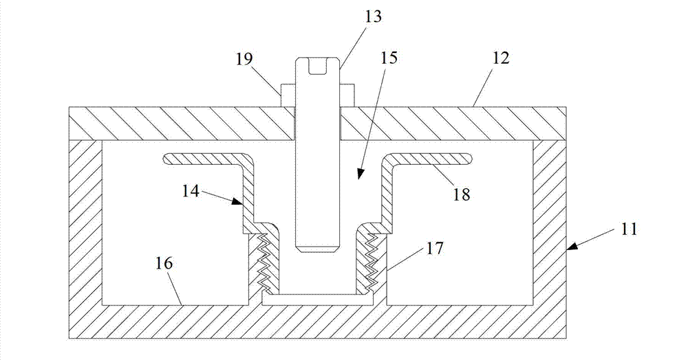
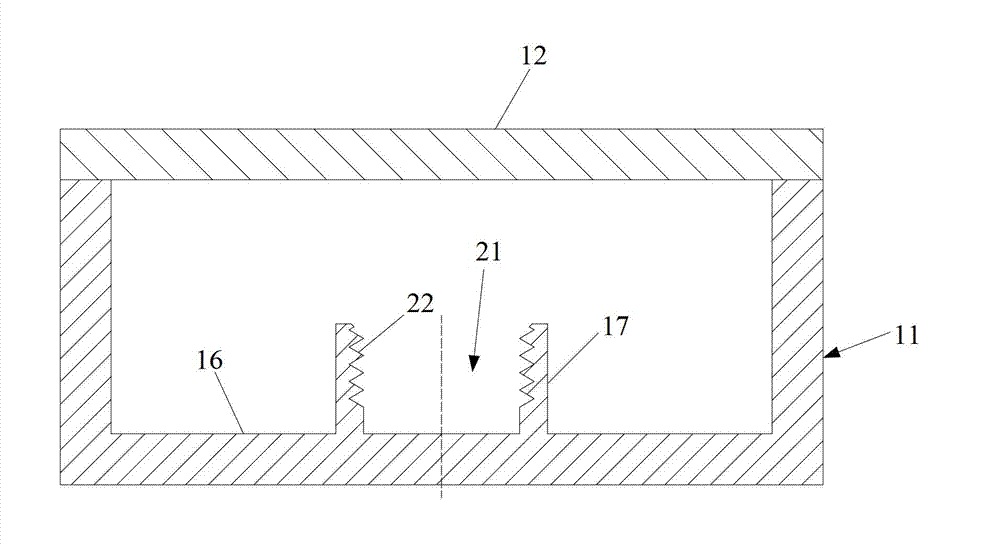
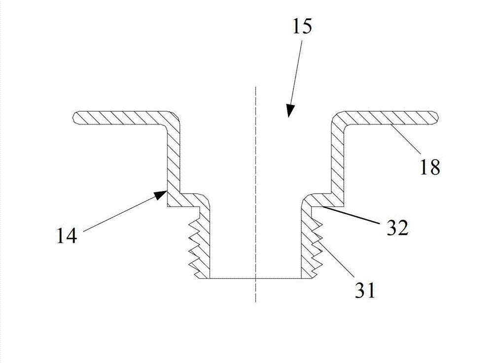
[0025] like figure 1 and Image 6 As shown, it is a specific embodiment of the cavity filter provided by the present invention. The cavity filter is a single-cavity filter, including a cavity 11 with an upper end opening, a cover plate 12, a tuning screw 13 and a resonant rod 14. The resonant rod 14 is fixed on the bottom plate 16 of the cavity 11 and accommodated in the cavity 11, the cover plate 12 can be fixedly installed at the opening of the cavity 11 by screw connection or weldin...


PUM


Abstract

The invention discloses a cavity filter, and relates to the communication technology to achieve the goal of enlarging the power capacity of the filter and the adjustment range of the frequency under the condition that the cavity depth of the filter is small. The cavity filter comprises a cavity with an upper end open, a cover plate, a tuning screw and a resonant rod, wherein the resonant rod is fixed on a baseplate of the cavity and is held inside the cavity, the cover plate is fixedly installed at the opening portion of the cavity and the cover plate is provided with a screw hole, the tuning screw matches with the screw hole, and one end of the tuning screw penetrates the cover plate and stretches into the cavity. A through hole is formed in the middle of the resonant rod, the tuning screw stretches into the through hole, and the outer wall of the resonant rod and the baseplate of the cavity are fixedly connected. The cavity filter enlarges the power capacity of the filter and the adjustment range of the frequency under the condition that the cavity depth of the filter is small.

Description

technical field [0001] The invention relates to communication technology, in particular to a cavity filter. Background technique [0002] A filter is a device that can process electromagnetic wave signals. Its main function is to allow useful signals to pass through without attenuation as much as possible, and to reflect unwanted signals as much as possible. At present, the cavity filter is generally used in the base station system to select the frequency of the transmitted signal or the received signal. A cavity filter usually includes a cavity, a resonant rod, a tuning screw and a cover plate. There are multiple cavities on the cavity. The resonant rod is combined with the cavity and accommodated in the cavity. The cover plate is installed at the opening of the cavity. There are multiple screw holes on the cover plate. The position of the screw hole is related to the resonance corresponding to the rod. The tuning screw fits with the screw hole, and one end of the tuning...

Claims


Application Information

Patent Timeline
Patent Type & Authority Applications(China)
IPC IPC(8): H01P1/207H01P7/00
CPCH01P1/207H01P7/06
Inventor 朱银虎袁进华朱其玉
Owner HUAWEI TECH CO LTD
Why Eureka
Try Eureka