A centrifugal separation drum machine

A technology of centrifugal separation and drum machine, which is applied in the direction of centrifuges and centrifuges with rotating drums, etc. It can solve the problems of accurately adjusting the amount of output, synchronous rotation, and small centrifuge processing capacity, and achieves easy replacement. Damaged parts, easy outlet flow, and high adjustment accuracy

Active Publication Date: 2020-05-15
YANGZHOU DAYANG WATER SUPPLY EQUIP
View PDF8 Cites 0 Cited by
  • Summary
  • Abstract
  • Description
  • Claims
  • Application Information

AI Technical Summary

Problems solved by technology

However, the laboratory centrifuge has a small processing capacity and cannot meet the requirements of most industrial production processing capacity.
At present, all centrifugal separation devices on the market cannot achieve the experimental results in the actual operation process. The reason is that the material cannot keep rotating synchronously with the equipment during the separation process, and the movement of the material depends on the friction between the material and the equipment. Disturbance, whether it is a vertical separation or a decanter centrifuge, the separation state is quite different from the laboratory, and it cannot achieve the relatively static state of the laboratory material separation, and the demulsification effect on oily materials is very poor
In the existing technology, especially the horizontal screw, the separation effect depends on the flocculation effect of the flocculant on the material, and its treatment effect and processing capacity depend on the adjustment of the feed amount, and the discharge is free discharge and cannot be adjusted; the existing technology does not have centrifugal demulsification Multifunctional centrifugal equipment for solid-liquid separation
Moreover, the drum machine in the prior art cannot accurately adjust the amount of material to be discharged, so that the adjustment of the separation rate, such as the moisture content, cannot be realized.
In addition, the centrifugal drum machine in the prior art cannot automatically adjust the size of the slag outlet, and at the same time cannot replace the wearing parts

Method used


Image

  • A centrifugal separation drum machine
  • A centrifugal separation drum machine
  • A centrifugal separation drum machine

Examples


Embodiment Construction

[0034] The present invention will be further described below in conjunction with the accompanying drawings and specific embodiments, but the protection scope of the present invention is not limited thereto.

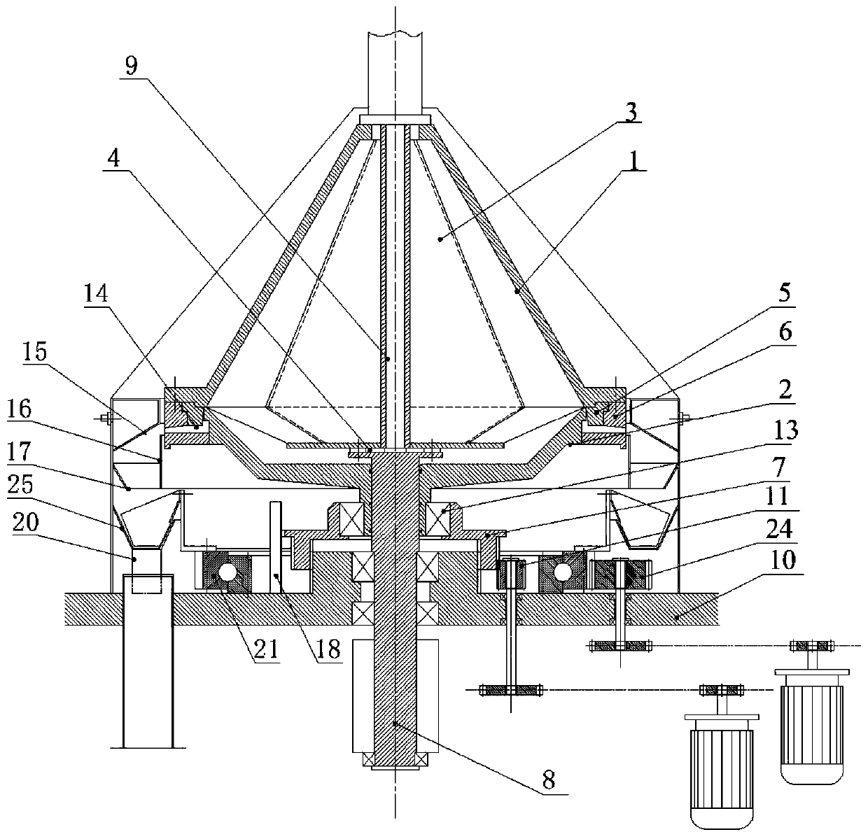
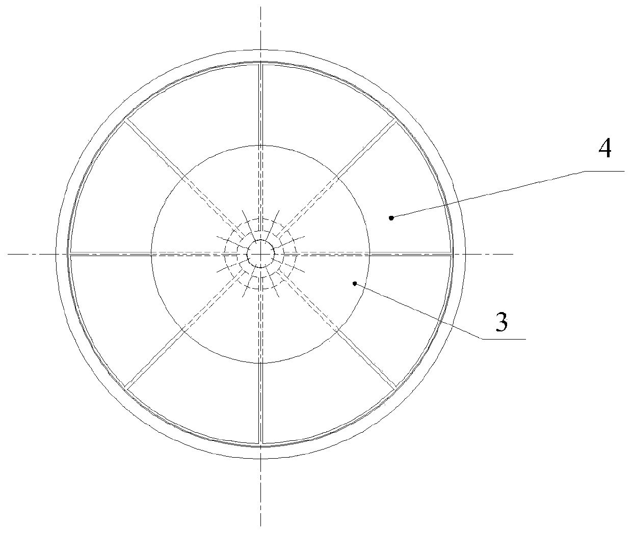
[0035] Such as figure 1 and figure 2 As shown, the centrifugal separation drum machine of the present invention includes an upper drum 1, a lower drum 2, a slag discharge retaining ring 5, a positioning ring 6, a drive shaft 8 and a rotating slag scraping system; the upper drum 1 The interior is divided into several separation chambers 3 in the radial direction, and the separation chamber 3 is provided with a liquid outlet at the top of the upper drum 1, and the upper drum 1 is provided with a feed pipe 9 inside, and the feed pipe 9 Located at the axial position of the upper drum 1, one end of the feed pipe 9 is connected to the top of the upper drum 1, and the other end of the feed pipe 9 is installed with the feed distribution plate 4, and the feed pipe 9 passes throu...


PUM


Abstract

The invention provides a centrifugal separation rotary drum machine. The centrifugal separation drum machine comprises an upper rotary drum, a lower rotary drum, a residue discharging stopping ring, alocating ring, a driving shaft and a rotary residue scraping system; the bottom of the upper rotary drum is connected with the locating ring, and the residue discharging stopping ring is installed atthe bottom of the upper rotary drum through a stopping opening of the locating ring; an inner ring of the locating ring is slidably connected with the lower rotary drum in the axial direction, the top of the lower rotary drum is in contact with the bottom of the upper rotary drum, and an outer ring of the lower rotary drum is in line seal cooperation with an inner ring of the residue dischargingstopping ring; a residue discharging opening is formed in the locating ring, and is in interdicted communication with several separation chambers through line seal; one end of the driving shaft is connected with a feeding distribution disc, and a sliding adjusting mechanism is installed outside an input shaft sleeve of the lower rotary drum; the rotary residue scraping system is installed on the base. By means of the centrifugal separation rotary drum machine, maintenance of the synchronous rotation speed of a separation medium and the rotary drums can be guaranteed, the medium is relatively static, disturbance cannot be generated, the separation state is identical to that of an experiment centrifugal machine, and the flow of solid-phase discharged residues can be randomly adjusted.

Description

technical field [0001] The invention relates to the field of drum machine equipment for both centrifugal demulsification and solid-liquid separation, in particular to a drum machine for centrifugal separation. Background technique [0002] As we all know, the vertical gravity discharge centrifuge is widely used in pharmaceutical, chemical, food and other industries. Its main function is to separate and dry the liquid components in the material. There is a bearing seat, a main shaft is arranged in the bearing seat, a drum body is set on the main shaft, a discharge port is provided at the lower part of the drum body, and a discharge hopper is provided below the discharge port; the drum body is provided with a cylindrical Drum, the cylindrical drum is provided with filter holes, the inner wall is provided with a filter screen, the base is provided with a ring-shaped liquid baffle, the outer side of the drum body is provided with an organic casing, and the gap between the liquid...

Claims


Application Information

Patent Timeline
Patent Type & Authority Patents(China)
IPC IPC(8): B04B1/08B04B11/02B04B11/06B04B15/00
CPCB04B1/08B04B11/02B04B11/06B04B15/00
Inventor 吴祥昌孙锋
Owner YANGZHOU DAYANG WATER SUPPLY EQUIP
Why Eureka
Try Eureka