Brightness blessing lamp structure

A technology of bright lights and lamp holders, applied in the field of bright lights, can solve the problems of unfavorable cost reduction and competitiveness, increased production costs, and uneven lighting

Inactive Publication Date: 2011-05-18
杨长杰
View PDF0 Cites 2 Cited by
  • Summary
  • Abstract
  • Description
  • Claims
  • Application Information

AI Technical Summary

Problems solved by technology

However, this kind of structure not only has many components and complex assembly, but also increases the production cost. At the same time, because the light source body 6 is a point light source (such as a light bulb, LED), the light irradiating it on the god statue 5 will cause brightness differences. Uniform shadows affect its overall visual effect and sense of dignity, which is the lack of its application
[0003] In addition, there is a structure disclosed in the No. M307363 "Bright Light" patent case in Taiwan, China, which mainly includes: a frame body, which is formed by combining two upright frames, a top frame and a bottom frame. The surface is provided with patterns that can be designed as characters or graphics; a casing is connected to the frame and has an open chamber facing the frame for accommodating a statue piece, which can be a protruding The flat plate of the three-dimensional pattern may be a carved three-dimensional statue; a panel, which is made of transparent material, is fixedly covered and closed on the open side of the chamber, so as to facilitate viewing of the statue in the chamber from the outside; a light source is arranged in the chamber The top side of the room is used to generate light to illuminate the statue; a frame is provided with several positioning holes for housing the housing; although this kind of structure can use the flat-shaped statue with its convex three-dimensional pattern, it is arranged on the The light source at the back of the statue reduces shadows when the light passes through the statue. However, it is still unavoidable to suffer from uneven lighting from some light sources, and its overall structure is more complicated, which is not conducive to cost reduction and competition. power boost

Method used


Image

  • Brightness blessing lamp structure
  • Brightness blessing lamp structure
  • Brightness blessing lamp structure

Examples


Embodiment Construction

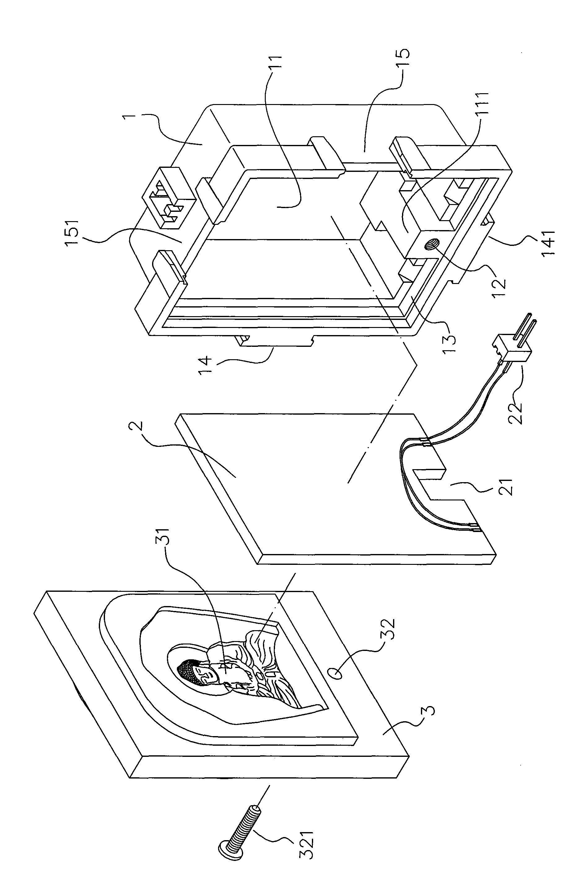
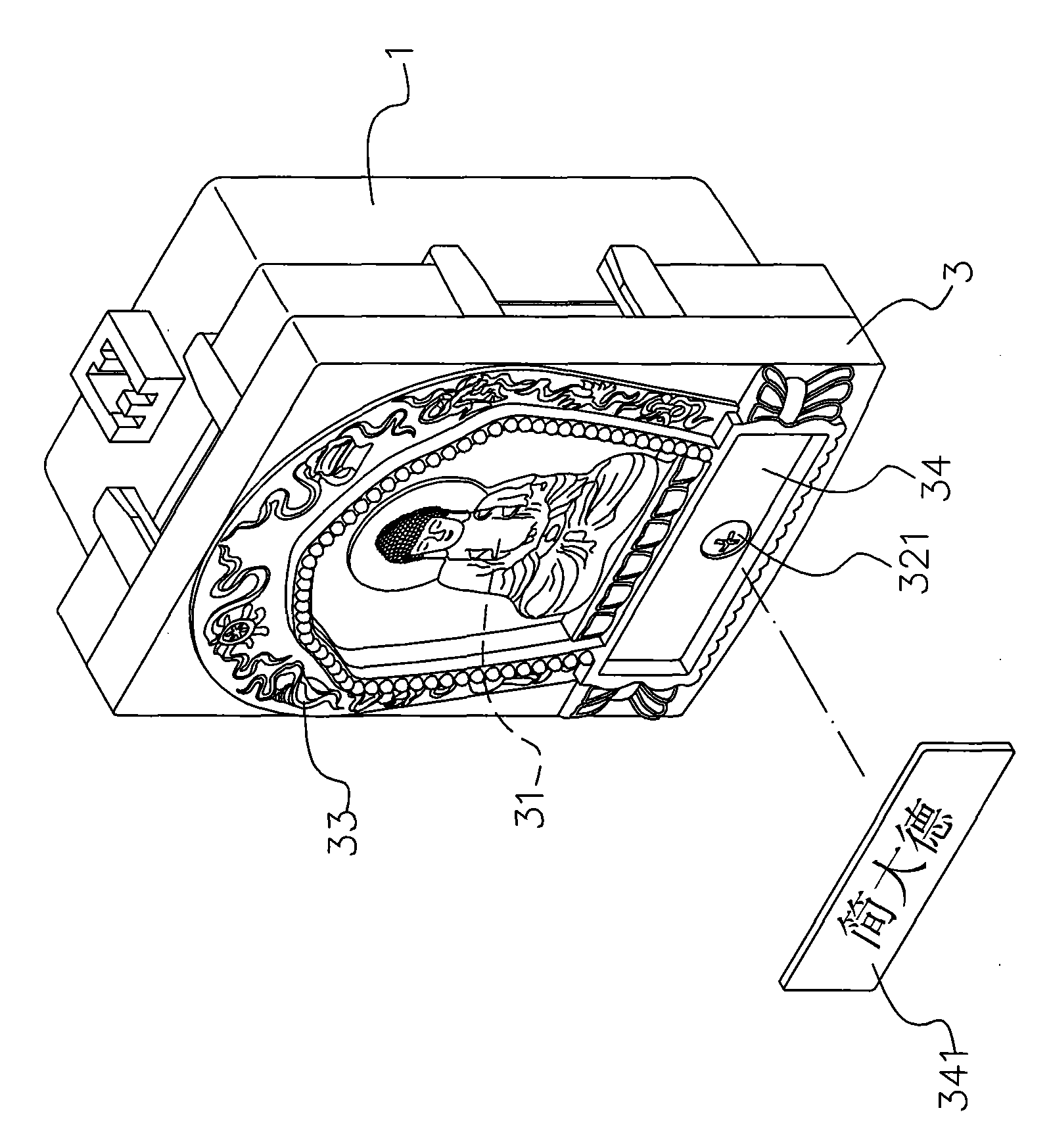
[0031] See Figure 2 to Figure 4 As shown, it can be clearly seen that the present invention mainly includes: a lamp holder 1, a light source body 2 and a light-transmitting panel 3 and other parts, wherein the lamp holder 1 is provided with an opening accommodating space 11, in the accommodating space 11 is provided with an inner convex portion 111 and a through hole 112 (located on the back side of the lamp holder 1), and a fixing hole 12 is provided on the side of the inner convex portion 111 near the opening, and the other is in the opening of the accommodating space 11. A ring flange 13 is provided on the peripheral side, and each opposite side of the outer peripheral edge of the lamp holder 1 is respectively provided with a positioning portion (which can be a male 14, 141) and a positioned portion (which can be a concave groove) that can be combined with each other. 15, 151), so that several lamp sockets can be stacked horizontally and vertically. The light source body ...


PUM


Abstract

The invention discloses a brightness blessing lamp structure, which mainly comprises an accommodating space with an opening, wherein the accommodating space is formed in a lamp holder; a sheet backlight assembly serving as a light source body is arranged in the accommodating space so as to generate uniformly scattered light rays; a transparent panel is arranged at the opening (on the front side of the light source body) of the accommodating space; three-dimensional religious patterns or characters (which can be recessed and are in layered recessed carved shapes) are arranged on the surface of one side of the transparent panel close to the accommodating space; and embossing patterns are arranged on the other side of the transparent panel. Therefore, the uniform light rays of the light source body pass through the three-dimensional religious patterns or characters, and special visual effect with three-dimensional shadows can be generated.

Description

Technical field: [0001] The present invention relates to a bright lamp structure, in particular to a bright lamp with simple structure, low cost and better texture and visual effect. Background technique: [0002] The known structure of light lamps is as figure 1 As shown, a box body 4 is provided with an accommodating space 41 with an opening, and a god statue 5 can be accommodated in the accommodating space 41, and a light source body 6 is arranged above the accommodating space 41, In order to provide the light source required for illuminating the statue 5, a transparent panel 7 can be covered on the opening of the accommodating space 41 to facilitate viewing the statue 5 in the accommodating space 41 from the outside, and the transparent panel 7 An outer frame 8 with embossed decorative patterns is fixed on the 7 peripheral sides to improve the texture of the overall box body. However, this kind of structure not only has many integral components and complicated assembly...

Claims


Application Information

Patent Timeline
Patent Type & Authority Applications(China)
IPC IPC(8): F21S2/00F21V1/00
Inventor 杨长杰
Owner 杨长杰
Why Eureka
Try Eureka