Marking structure and electronic device

A technology of identification and light guide plate, applied in display devices, illuminated signs, instruments, etc., can solve the problems of low light use efficiency and reduced user experience, etc.

Active Publication Date: 2019-01-04
TCL TECH ELECTRONICS (HUIZHOU) CO LTD
View PDF15 Cites 2 Cited by
  • Summary
  • Abstract
  • Description
  • Claims
  • Application Information

AI Technical Summary

Problems solved by technology

The existing sign structure usually adopts a side-type backlight structure, and the light source of the side-type light guide plate mostly uses a lamp tube or a light-emitting diode, and the light emitted by the lamp tube or light-emitting diode is incident on the side of the light guide plate, so the bright...

Method used


Image

  • Marking structure and electronic device
  • Marking structure and electronic device
  • Marking structure and electronic device

Examples


Embodiment Construction

[0028] The following will clearly and completely describe the technical solutions in the embodiments of the present invention with reference to the accompanying drawings in the embodiments of the present invention. Obviously, the described embodiments are only part of the embodiments of the present invention, not all of them. Based on the embodiments of the present invention, all other embodiments obtained by persons of ordinary skill in the art without creative efforts fall within the protection scope of the present invention.

[0029] It should be noted that all directional indications (such as up, down, left, right, front, back...) in the embodiments of the present invention are only used to explain the relationship between the components in a certain posture (as shown in the accompanying drawings). Relative positional relationship, movement conditions, etc., if the specific posture changes, the directional indication will also change accordingly.

[0030] In addition, the ...


PUM


Abstract

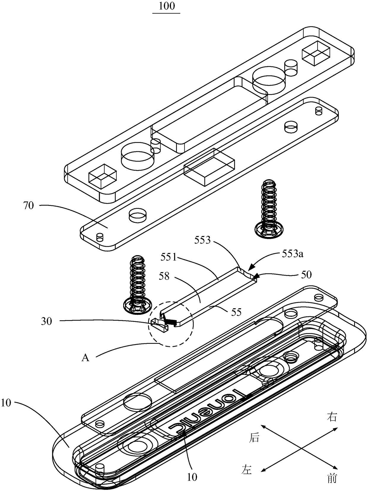
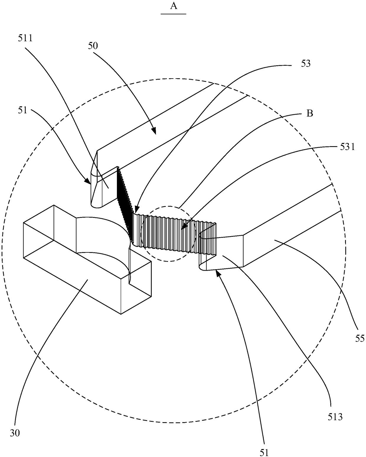
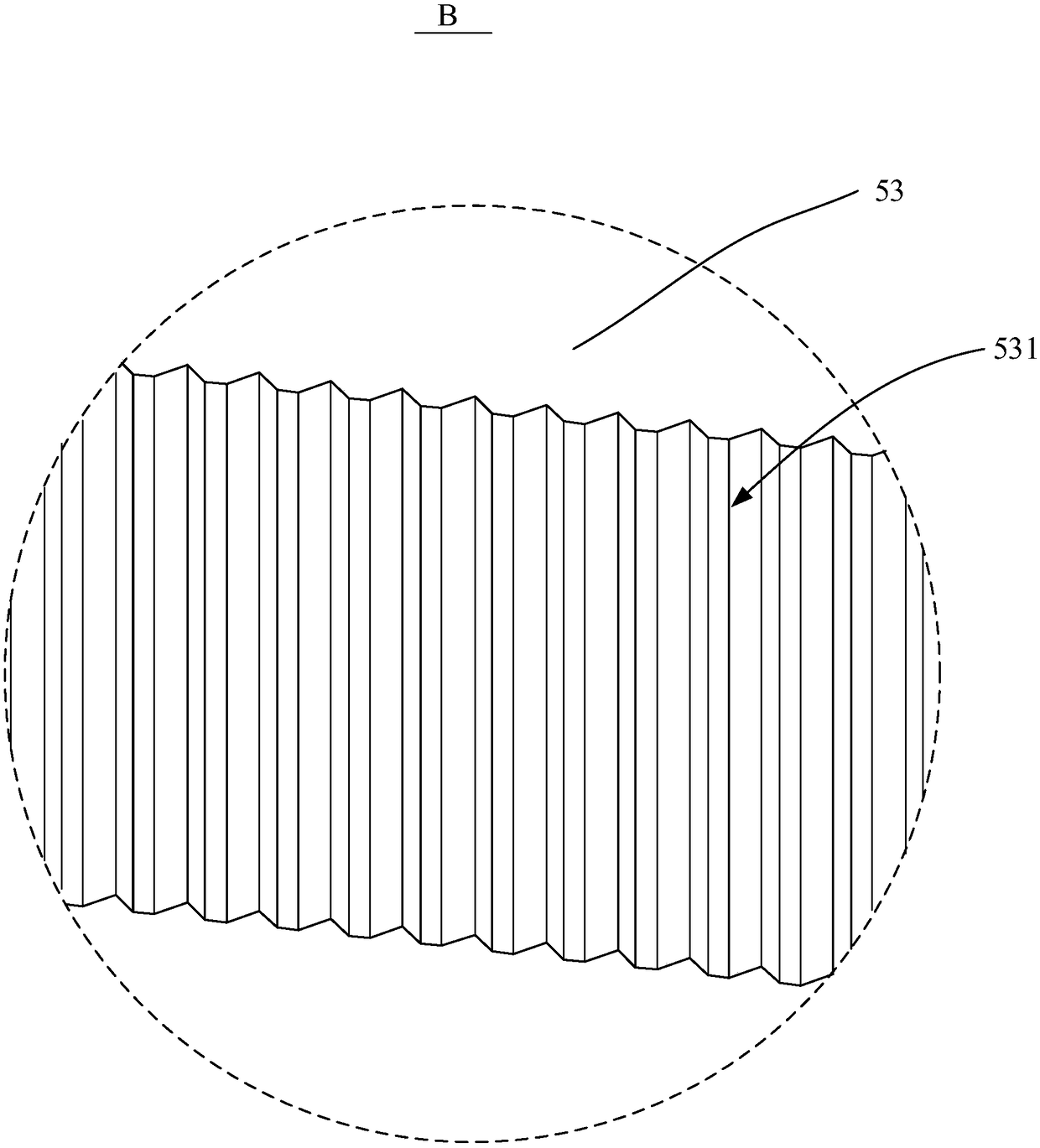
The invention discloses a marking structure and an electronic device, wherein, the marking structure comprises a box body, a marking hole is arranged on the box body, and a light source and a light guide plate are accommodated in the box body. The light guide plate is accommodated in that box body and exposes the light of the light source at the mark hole, one side of the light guide plate is opposite to the light source, and the light guide plate is protruded toward the side surface of the light source with two protruding parts and a light condensing part. A light condensing section focuses incoming light rays of a light source on a central axis of the light guide plate, a plurality of tooth-shaped protrusions are protruded toward the surface of the light source, two protrusions are respectively located on opposite sides of the light condensing portion, and the protrusions include an incident surface and a total reflection surface, the incident surface faces the light condensing portion, and the total reflection surface faces away from the light condensing portion. The marking structure provided by the invention improves the utilization rate of light energy, improves the light intensity and uniformity of the light guide plate, improves the user experience, and further reduces the cost.

Description

technical field [0001] The invention relates to the technical field of product identification, in particular to an identification structure and an electronic device containing the identification structure. Background technique [0002] LOGO (logo) is an essential part of audio, TV and other electronic products. As users have higher and higher requirements for product logos, many product logos begin to use luminous effects to enhance the appearance and visual experience of products. The existing sign structure usually adopts a side-type backlight structure, and the light source of the side-type light guide plate mostly uses a lamp tube or a light-emitting diode, and the light emitted by the lamp tube or light-emitting diode is incident on the side of the light guide plate, so the brightness of the light guide plate It will decrease with the increase of the lateral distance from the light-emitting element, and the efficiency of light use is not high. As a result, the logo stru...

Claims


Application Information

Patent Timeline
IPC IPC(8): G09F13/04G09F13/14
CPCG09F13/04G09F13/14G09F13/0418G09F13/0422
Inventor 蔡亲明
Owner TCL TECH ELECTRONICS (HUIZHOU) CO LTD
Why Eureka
Try Eureka