Centrifugal separation drum machine

A drum machine and drum technology, applied in centrifuges and other directions, can solve the problems of precise adjustment of the amount of material discharged, synchronous rotation, and inability to maintain equipment, etc., to achieve the effects of easy control, high adjustment accuracy, and large adjustment margin.

Active Publication Date: 2018-09-28
YANGZHOU DAYANG WATER SUPPLY EQUIP
View PDF8 Cites 2 Cited by
  • Summary
  • Abstract
  • Description
  • Claims
  • Application Information

AI Technical Summary

Problems solved by technology

However, the laboratory centrifuge has a small processing capacity and cannot meet the requirements of most industrial production processing capacity.
At present, all centrifugal separation devices on the market cannot achieve the experimental results in the actual operation process. The reason is that the material cannot keep rotating synchronously with the equipment during the separation process, and the movement of the material depends on the friction between the material and the equipment. Disturbance, whether it is a vertical separation or a decanter centrifuge, the separation state is quite different from the laboratory, and it cannot achieve the relatively static state of the laboratory material separation, and the demulsification effect on oily materials is very poor
In the existing technology, especially the horizontal screw, the separation effect depends on the flocculation effect of the flocculant on the material, and its treatment effect and processing capacity depend on the adjustment of the feed amount, and the discharge is free discharge and cannot be adjusted; the existing technology does not have centrifugal demulsification Multifunctional centrifugal equipment for solid-liquid separation
Moreover, the drum machine in the prior art cannot accurately adjust the amount of material to be discharged, so that the adjustment of the separation rate, such as the moisture content, cannot be realized.

Method used


Image

  • Centrifugal separation drum machine
  • Centrifugal separation drum machine
  • Centrifugal separation drum machine

Examples


Embodiment Construction

[0024] The present invention will be further described below in conjunction with the accompanying drawings and specific embodiments, but the protection scope of the present invention is not limited thereto.

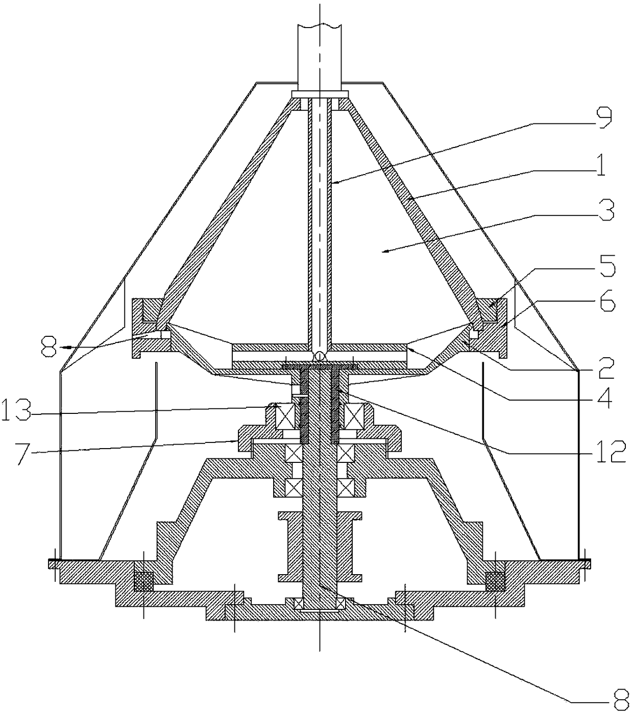
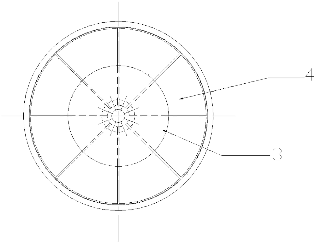
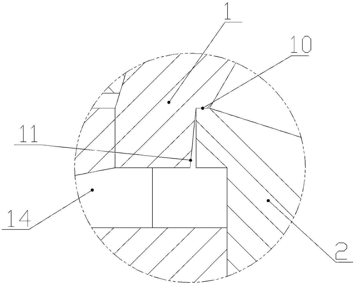
[0025] Such as figure 1 and figure 2 As shown, the centrifugal separation drum machine of the present invention includes an upper drum 1, a lower drum 2, a stop ring 5, a positioning ring 6 and a drive shaft 8; the inside of the upper drum 1 is radially uniform Divided into a number of separation chambers 3, the separation chamber 3 is provided with a liquid outlet on the top of the upper drum 1, the inside of the upper drum 1 is provided with a feed pipe 9, and the feed pipe 9 is located at the top of the upper drum. Drum 1 axis position, one end of the feed pipe 9 is connected to the top of the upper drum 1, the other end of the feed pipe 9 is installed with the feed distribution plate 4, and the feed pipe 9 passes through the feed distribution plate 4 and the Severa...


PUM


Abstract

The invention provides a centrifugal separation drum machine. The centrifugal separation drum machine comprises an upper drum, a lower drum, a limiting retainer ring, a positioning ring and a drivingshaft; the internal of the upper drum is equally divided into multiple separation chambers in the radial direction; a feed pipe is arranged in the upper drum; one end of the feed pipe is connected with the top of the upper drum; a feed distribution disc is mounted at the other end of the feed pipe; the bottom of the upper drum is contacted with the lower drum through a stop port; the limiting retainer ring is mounted at the external of the upper drum; an inner ring of the positioning ring is slidingly connected with the lower drum; the positioning ring is connected with the limiting retainer ring; a slag outlet and the multiple separation chambers do not communicate through a stop port sealing surface; an inner hole of an input shaft sleeve of the lower drum is connected with the driving shaft; and a slide adjusting mechanism is mounted at the external of the input shaft sleeve of the lower drum. The centrifugal separation drum machine can guarantee maintenance of synchronous rotatingspeed of a separation medium and the drums; the medium is relatively static without generating disturbance; the separation state is the same with an experiment centrifuge; and the solid-phase slag outlet flow can be randomly adjusted.

Description

technical field [0001] The invention relates to the field of drum machine equipment for both centrifugal demulsification and solid-liquid separation, in particular to a drum machine for centrifugal separation. Background technique [0002] As we all know, the vertical gravity discharge centrifuge is widely used in pharmaceutical, chemical, food and other industries. Its main function is to separate and dry the liquid components in the material. There is a bearing seat, a main shaft is arranged in the bearing seat, a drum body is set on the main shaft, a discharge port is provided at the lower part of the drum body, and a discharge hopper is provided below the discharge port; the drum body is provided with a cylindrical Drum, the cylindrical drum is provided with filter holes, the inner wall is provided with a filter screen, the base is provided with a ring-shaped liquid baffle, the outer side of the drum body is provided with an organic casing, and the gap between the liquid...

Claims


Application Information

Patent Timeline
IPC IPC(8): B04B7/08B04B9/12B04B11/04
CPCB04B7/08B04B9/12B04B11/04
Inventor 吴祥昌孙锋
Owner YANGZHOU DAYANG WATER SUPPLY EQUIP
Why Eureka
Try Eureka