Method and arrangement for real time monitoring laser luminous spot and light path automatically collimating

A laser spot and real-time monitoring technology, applied in the laser field, can solve the problems of slow stepping motor control feedback process, long movement time system requirements, low optical path adjustment accuracy, etc., to achieve reduced spot drift, compact structure, and high adjustment accuracy Effect

Inactive Publication Date: 2007-10-31
SHANGHAI INST OF OPTICS & FINE MECHANICS CHINESE ACAD OF SCI
View PDF0 Cites 33 Cited by
  • Summary
  • Abstract
  • Description
  • Claims
  • Application Information

AI Technical Summary

Problems solved by technology

The structure of this collimation system is complicated, and the feedback process of the stepping motor control is relatively slow. It takes a few minutes to complete an optical path adjustment, and the adjustment accuracy of the optical path is not high. It cannot meet the requirements for a high repetition rate laser system. For example, in a laser system with a repetition rate of 1kHz, the stepper motor cannot meet the system requirements at all due to its long movement time.

Method used


Image

  • Method and arrangement for real time monitoring laser luminous spot and light path automatically collimating

Examples


Embodiment Construction

[0032] The present invention will be further described below in conjunction with the embodiments and accompanying drawings, but the protection scope of the present invention should not be limited thereby.

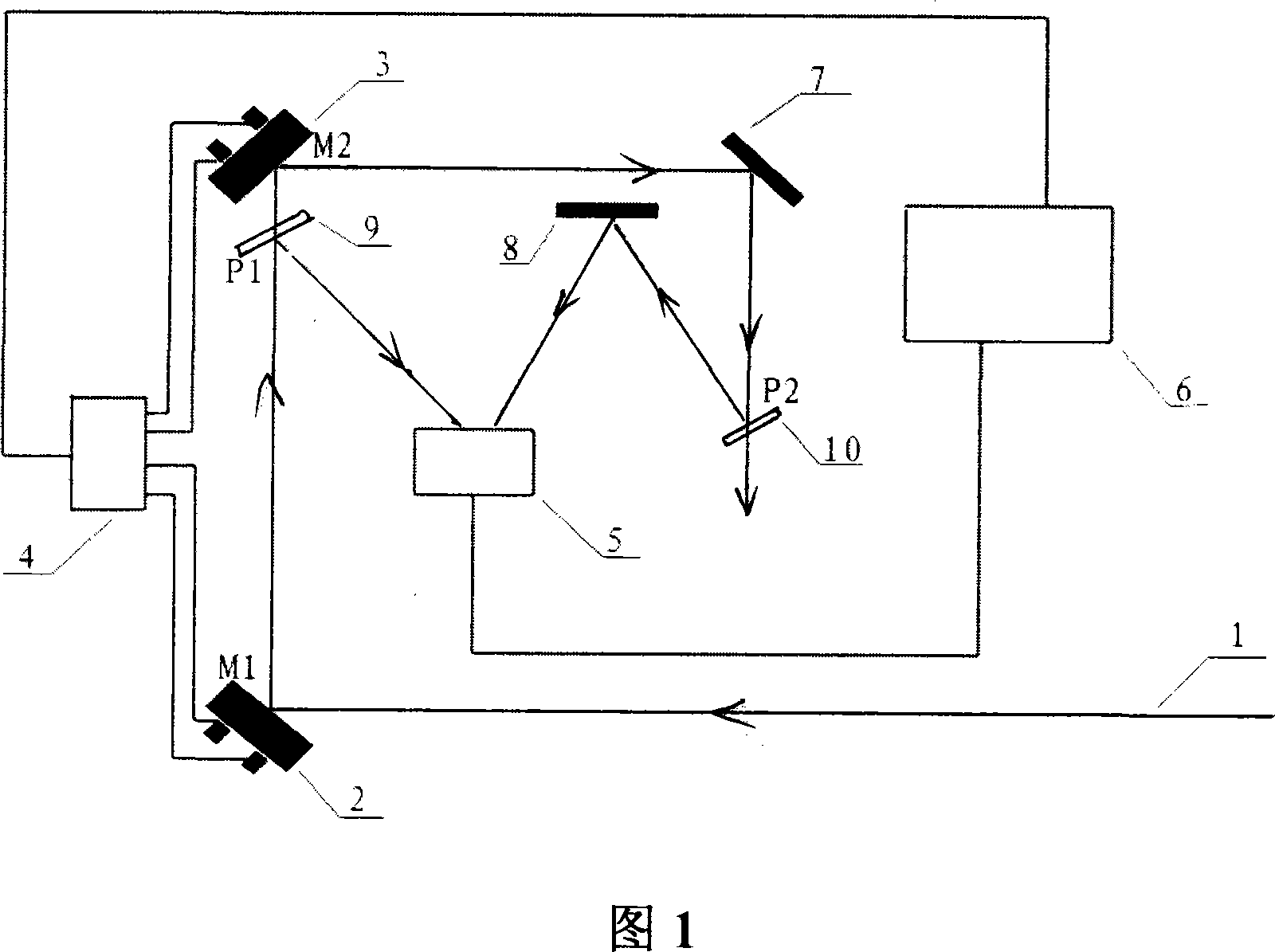
[0033] Please refer to FIG. 1 first. FIG. 1 is a schematic diagram of a device for real-time monitoring of laser spot and automatic alignment of optical path for implementing the method of the present invention. As can be seen from the figure, the laser spot real-time monitoring and automatic collimation device of the present invention is characterized in that it includes: a first piezoelectric ceramic electric mirror frame 2 with a first 45° total reflection mirror M1 and a second 45° total reflection mirror M2 The second piezoelectric ceramic electric mirror frame 3, the output end of a driver 4 is respectively connected to the control end of the first piezoelectric ceramic electric mirror frame 2 and the second piezoelectric ceramic electric mirror frame 3, and the input ...


PUM


Abstract

This invention relates to one laser spot real time monitor and light path automatic calibration method and device, which uses single CCD camera head to collect laser spot, piezoelectricity electrical lens rack automatic calibration path by use of computer for spot process and real time monitor, wherein the device monitor spot frequency is about 10Hz and feedback control frequency is of 1Hz to eliminate and lower shake circle for float more than one second with stability less than 0. 5 micro arc degree in calibration laser space.

Description

technical field [0001] The invention relates to laser, which is a method and device for real-time monitoring of laser spot and automatic alignment of optical path. It can be applied to any optical system that needs spot monitoring and automatic alignment of light beam. The optical system can be automatically adjusted by piezoelectric ceramic electric mirror frame. The optical path, the spatial stability of the laser beam after collimation is less than 0.5 micro radians, which can be applied to various optical systems and experimental research fields that require precise and stable light spots. Background technique [0002] In the development of optical technology, the requirements for the stability of laser energy, pulse width stability and spatial pointing stability have also been continuously improved. The spatial pointing stability of the laser spot is very important for the stability of the laser output of the system, and many physical experiments, such as hollow-core fi...

Claims


Application Information

Patent Timeline
Patent Type & Authority Applications(China)
IPC IPC(8): G02B27/30G05B19/048G05D3/20
Inventor 尉鹏飞刘军李小芳陈晓伟刘鹏曾志男李儒新
Owner SHANGHAI INST OF OPTICS & FINE MECHANICS CHINESE ACAD OF SCI
Why Eureka
Try Eureka