

Structural arrangement for battery for saddle-ridden vehicle
A straddle-type vehicle and configuration structure technology, which is applied in the field of battery configuration structure, can solve the problems of increasing the weight of the frame, increasing the frame, and intensifying the bending, and achieves the effect of realizing light weight, improving the spanning ability, and smoothing the bending.
- Summary
- Abstract
- Description
- Claims
- Application Information
AI Technical Summary
Problems solved by technology
Method used
Image

Examples
no. 1 approach
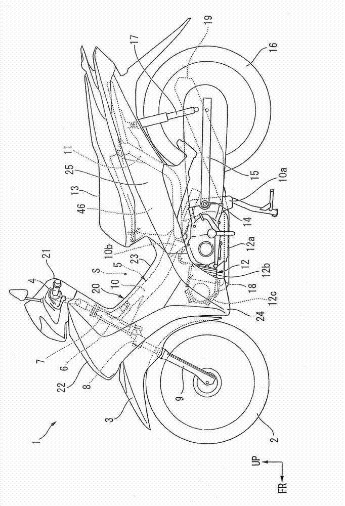
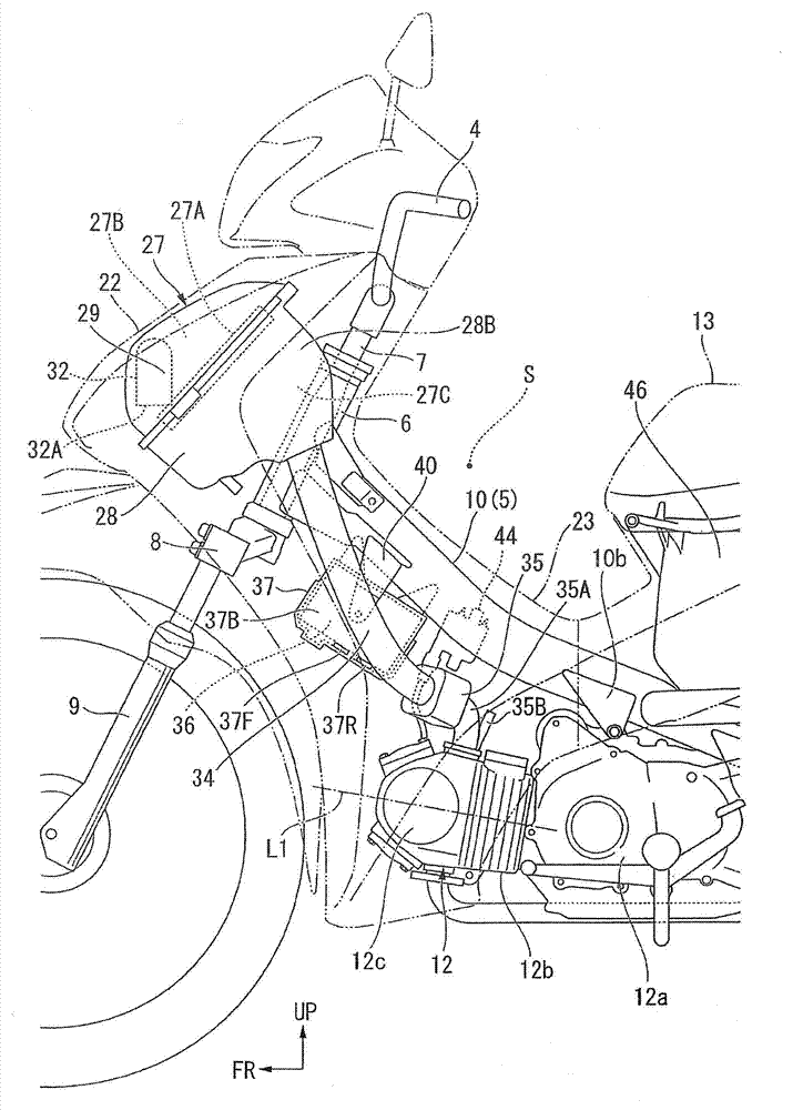
[0074] figure 1 2 shows a motorcycle 1 as a straddle-type vehicle to which the configuration according to the first embodiment of the present invention is applied. First, a rotatable front wheel 2 is provided at the front of the motorcycle 1 , and a front fender 3 is provided above the front wheel 2 . Above the front fender 3, a handle 4 for turning the front wheel 2 is provided, and the handle 4 is arranged on the upper part of the steering shaft 7, which is supported by the head pipe 6 formed at the front end of the vehicle frame 5 so as to be able to rotate.
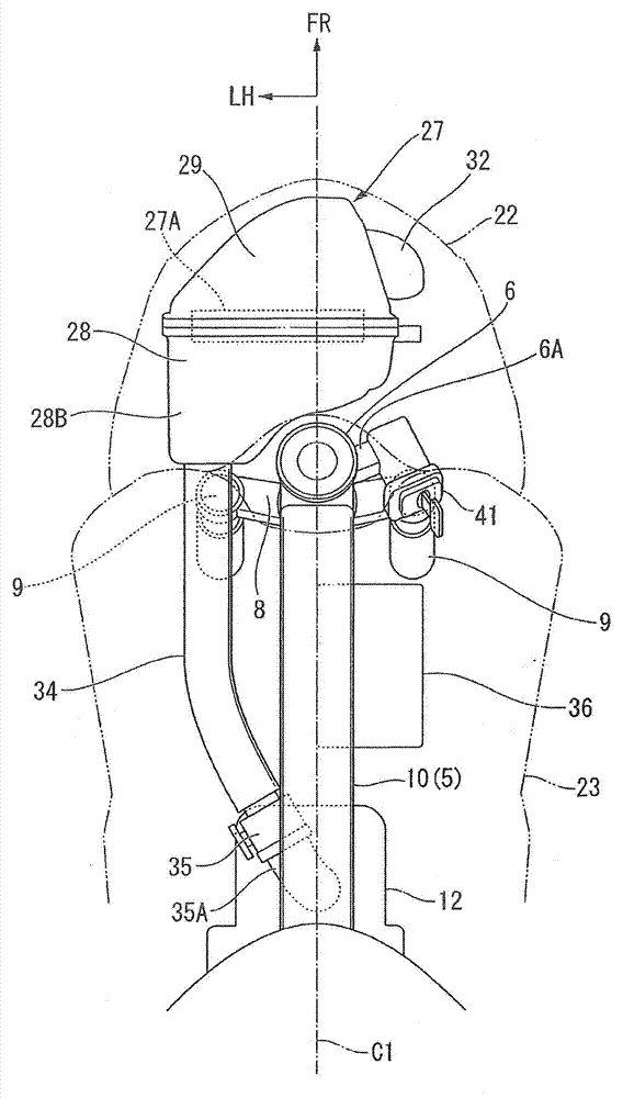
[0075] A plate-shaped lower bridge 8 extending left and right is provided on the lower portion of the steering shaft 7 , and upper ends of a pair of left and right front forks 9 , which rotatably support the front wheel 2 at the lower portion, are fixed to the left and right ends of the lower bridge 8 . That is, the front fork 9 is positioned below the head pipe 6 .
[0076] The vehicle frame 5 is provided with: a ...
no. 2 approach
[0101] Next, a second embodiment of the present invention will be described. Figure 9 The upper surface of the motorcycle 50 according to this embodiment is shown in . In addition, below, the same code|symbol is attached|subjected to the same part as 1st Embodiment, and description is abbreviate|omitted, and it demonstrates centering on the difference from 1st Embodiment.
[0102] like Figure 9 As shown, on the rear left side of the air cleaner case 28 , a bulging portion 28B similar to that of the first embodiment bulging toward the rear is formed, and a connecting pipe 51 is connected to the rear surface of the bulging portion 28B. The connecting pipe 51 passes through the left side of the head pipe 6 and passes above the left front fork 9 .
[0103] Here, if by Figure 9 As clearly shown, in the present embodiment, the connection pipe 51 passes through the side of the head pipe 6 on the inside of the outer end 8A of the lower bridge 8 and on the inside of the outer end...
no. 3 approach
[0107] Next, a third embodiment of the present invention will be described. Figure 10 ~ Figure 12 The left side, the upper surface, and the right side of the motorcycle 60 which concerns on this embodiment are shown in . In addition, below, the same code|symbol is attached|subjected to the same part as 1st Embodiment, and description is abbreviate|omitted, and it demonstrates centering on the difference from 1st Embodiment.
[0108]In the present embodiment, the engine 12 is of a carburetor type, and the motorcycle 60 includes an air cleaner 61 , a connection pipe 62 , and a carburetor 63 . Form the suction system. On the left side of the rear part of the air cleaner case 64 of the air cleaner 61, a bulging part 64B bulging toward the rear and an extended bulging part 66 extending rearward from the bulging part 64B are integrally formed. Furthermore, the air cleaner 61 includes: an air cleaner cover 65 that is detachably attached to the air cleaner case 64; and a space form...
PUM
 Abstract
Description
Claims
Application Information