
Winding core, winding reel and band-winding method

A technology for winding tapes and tapes, which is applied in the direction of winding strips, packaging, and conveying filamentous materials, etc. It can solve the problems of package deformation, impact failure, bending, etc., and achieve cost reduction and prevent winding collapse. Effect

Active Publication Date: 2013-05-08
SHIN-ETSU POLYMER CO LTD
View PDF6 Cites 6 Cited by
  • Summary
  • Abstract
  • Description
  • Claims
  • Application Information

AI Technical Summary

Problems solved by technology

[0009] The existing reel for winding is constituted as described above, and is wound in such a manner that one side of the carrier tape 10 is simply overlapped with the other side of the already wound carrier tape 10 . In overlapping winding, the side portion of the carrier tape 10 is inclined with respect to the peripheral surface 2A of the winding core 1A, and the winding length is different, and the carrier tape 10 is easily deformed and bent in a certain direction in the package.
[0010] As a result, errors may occur when positioning the pocket 12 of the carrier tape 10 and inserting the electronic component into the pocket 12, affecting the operation of bonding the cover tape to the surface of the band 11 of the carrier tape 10, and making it impossible to insert the electronic component during mounting of the electronic component. The carrier tape 10 is pulled out smoothly

Method used


Image

  • Winding core, winding reel and band-winding method
  • Winding core, winding reel and band-winding method
  • Winding core, winding reel and band-winding method

Examples


Embodiment )

[0096] Hereinafter, examples of the winding core, winding reel, and tape body winding method of the present invention will be described together with comparative examples.

Embodiment 1)

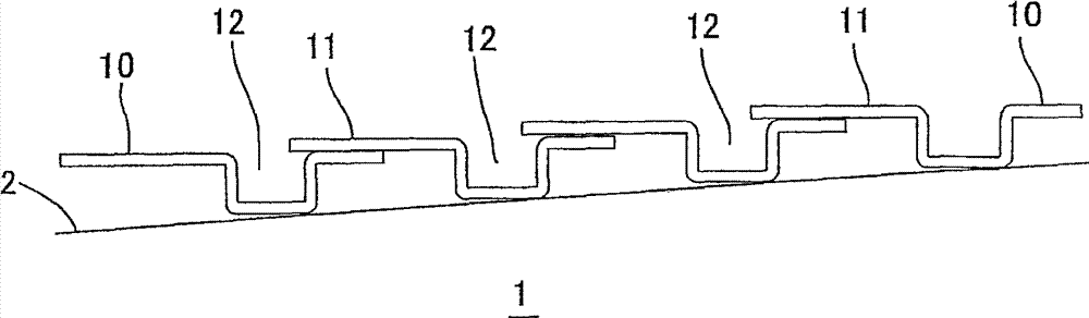
[0098] First, an empty winding core is fitted to the drive shaft of the winding device, the end of the carrier tape is wound on the winding core, and the carrier tape is wound around the guide roller of the winding device under tension. On the peripheral surface of the winding core, a 1.5° taper is formed in the radially outward direction. In addition, as the carrier tape, a tape width of 8 mm, a depth of each pocket of 1.42 mm, and a type in which a plurality of perforations were perforated at intervals on one side in the longitudinal direction of the tape were used.

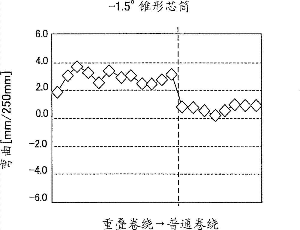
[0099] After the carrier tape is wound on the guide roller of the winding device, the winding device is driven to wind the carrier tape to the peripheral surface of the winding core while moving to the left or right, and the bending of the carrier tape is measured, and Summarize the results of this measurement in the Figure 14 , Figure 15 in the chart. During the winding of the carrier tape, such as Figu...

Embodiment 2)

[0103] It is basically the same as in Example 1, but a 5° taper is formed on the peripheral surface of the winding core in the radially outward direction. Others measure the bending of carrier tape identically with embodiment 1, and its measurement result is summarized in Figure 14 , Figure 16 in the chart. Figure 16 The dotted line near the center of indicates the change point of the carrier tape from the overlapping winding to the normal winding.

[0104] As a result of measuring the warp of the carrier tape, the warp of the carrier tape was small, and extremely good results were obtained.


PUM


Abstract

Provided are a winding core, a winding reel and a band-winding method, which are capable of preventing the band from being easily bent in a certain direction when the band is inclined to generate a difference in winding length, causing strain in winding around the band. When a carrier tape (10) is traversely wound on a curved peripheral surface (2), the peripheral surface (2) is inclined radially outward with movement from one end section toward the other end section by a cylindrical winding core (1) which overlaps one side section of the carrier tape (10) on the other side section of the wound carrier tape (10) and winds the overlapped carrier tape (10), and an inclination (?) of the peripheral surface (2) is made to base on 0< [theta]<=2arctan (the thickness / traverse pitch of the carrier tape). The peripheral surface (2) of the winding core (1) is inclined in the opposite direction from the inclination of the overlapped section of the carrier tape (10), thus making it possible to relax the inclination of the overlapped section of the carrier tape (10).

Description

technical field [0001] The present invention relates to a winding core used for winding a tape such as a carrier tape, a winding reel, and a tape winding method. Background technique [0002] The carrier tape used for mounting electronic components on the circuit board is wound on the winding core of the winding reel. Here, in the production process of the carrier tape and the storage process of the electronic components, from the viewpoint of reducing the replacement frequency of the winding reel and improving production efficiency, a longer carrier tape is wound. Such as Figure 21 and Figure 22 As shown, such a winding reel includes a winding core 1A and a carrier tape 10 that is wound on the winding core 1A so as to move laterally and accommodates a plurality of electronic components. [0003] Such as Figure 21 and Figure 22 As shown, the winding core 1A is formed in a cylindrical shape, has flanges 3 on both left and right end faces, and has a width larger than th...

Claims


Application Information

Patent Timeline
IPC IPC(8): B65H75/14B65D73/02B65H75/26
CPCB65H75/14B65H2701/3914B65H2701/37B65D85/672B65H54/103B65D73/02B65H18/08B65H75/26
Inventor 中田悠贵
Owner SHIN-ETSU POLYMER CO LTD
Features
  • Generate Ideas
  • Intellectual Property
  • Life Sciences
  • Materials
  • Tech Scout
  • Unparalleled Data Quality
  • Higher Quality Content
  • 60% Fewer Hallucinations
Learn More