Sound source separator device, sound source separator method, and program

A technology for separating devices and sound sources, which is applied in the directions of sound-producing equipment, speech analysis, and microphone signal combination, etc., can solve the problems of poor call quality, poor performance, poor recognition performance, etc., and achieve the effect of reducing music noise.

Inactive Publication Date: 2013-05-08
ASAHI KASEI KK
View PDF6 Cites 36 Cited by
  • Summary
  • Abstract
  • Description
  • Claims
  • Application Information

AI Technical Summary

Problems solved by technology

Due to the progress of current speech recognition technology, for the problem of speech recognition rate degradation relative to steady-state noise, it is possible to recover a considerable part of the degraded performance
However, as a problem that is difficult to deal with with the existing voice recognition technology, there is a problem that the recognition performance deteriorates when multiple speakers speak at the same time.
If the existing voice recognition technology is used, because the technology of recognizing the mixed voice of two people who speak at the same time is relatively low, when the voice recognition device is used, the voices of the passengers other than the voicer will be restricted, and the actions of the passengers will be restricted. situation
[0004] Also, with regard to a mobile phone or a headset that can be connected to a mobile phone for hands-free calls, the deterioration of the call quality will also occur when the call is made in an environment of background noise.

Method used


Image

  • Sound source separator device, sound source separator method, and program
  • Sound source separator device, sound source separator method, and program
  • Sound source separator device, sound source separator method, and program

Examples


Embodiment Construction

[0049] Hereinafter, embodiments according to the present invention will be described with reference to the drawings.

[0050] [First Embodiment]

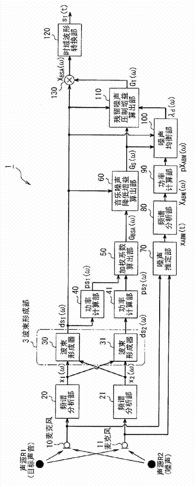
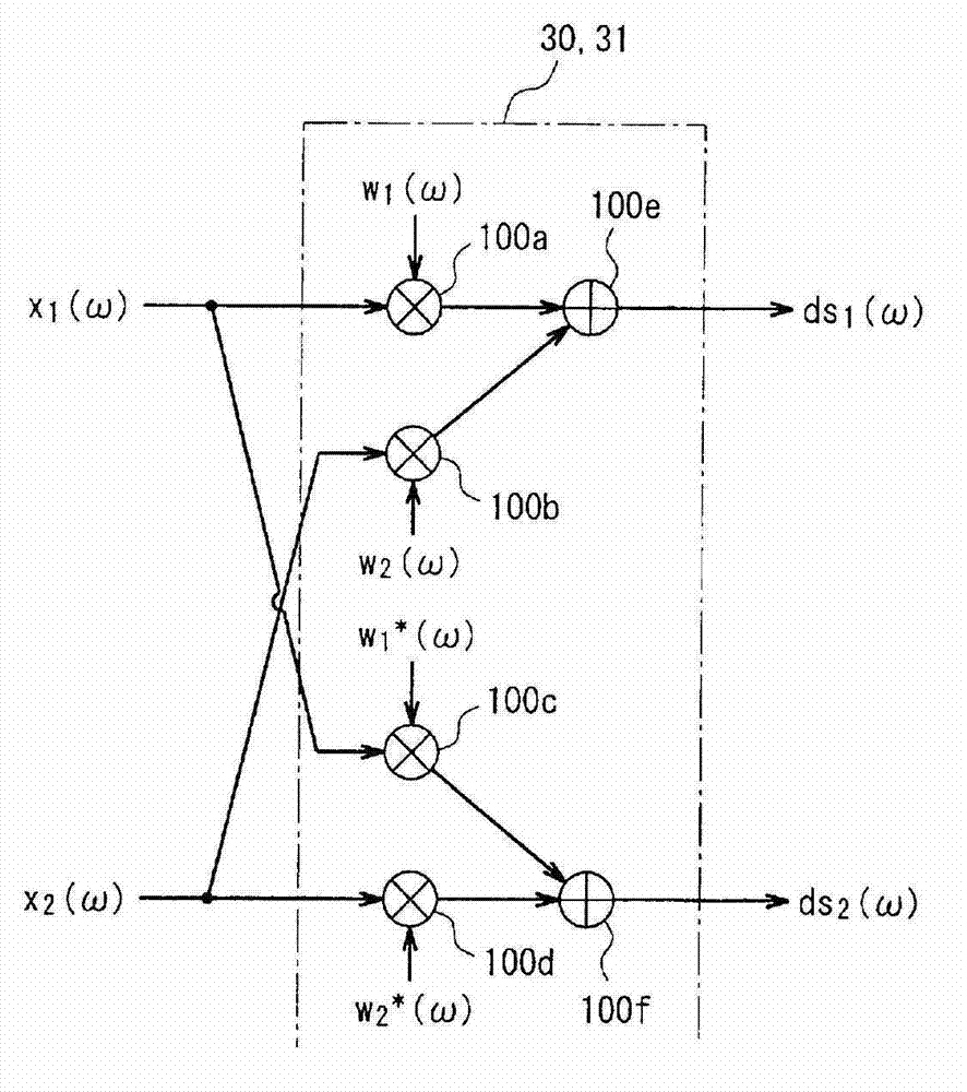
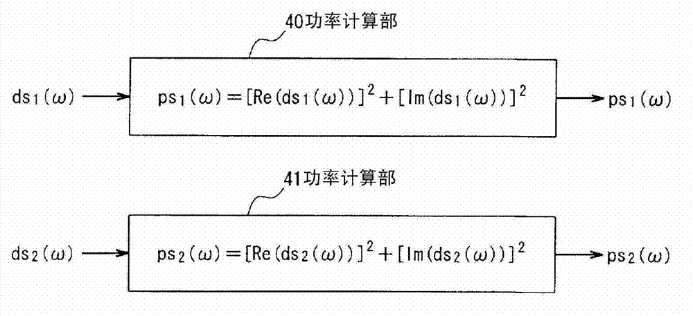
[0051] figure 1 It is a figure of the basic structure of the sound source separation system concerning 1st Embodiment. The system includes two microphones (hereinafter referred to as “microphones”) 10 , 11 , and a sound source separation device 1 . Hereinafter, the embodiment will be described assuming that there are two microphones, but the number of microphones may be at least two or more, and is not limited to two.

[0052] This sound source separation device 1 has: hardware including a CPU, not shown, which controls the whole and executes calculation processing, and a storage device such as a ROM, RAM, and hard disk device; and programs, data, etc. stored in the storage device. software. Each functional block of the sound source separation device 1 is realized by these hardware and software.

[0053] The two microphones 10,...


PUM


Abstract

With conventional source separator devices, specific frequency bands are significantly reduced in environments where dispersed static is present that does not come from a particular direction, and as a result, the dispersed static may be filtered irregularly without regard to sound source separation results, giving rise to musical noise. In an embodiment of the present invention, by computing weighting coefficients which are in a complex conjugate relation, for post-spectrum analysis output signals from microphones (10, 11), a beam former unit (3) of a sound source separator device (1) thus carries out a beam former process for attenuating each sound source signal that comes from a region wherein the general direction of a target sound source is included and a region opposite to said region, in a plane that intersects a line segment that joins the two microphones (10, 11). A weighting coefficient computation unit (50) computes a weighting coefficient on the basis of the difference between power spectrum information calculated by power calculation units (40, 41).

Description

technical field [0001] The present invention relates to a sound source separation device that uses a plurality of microphones to separate a sound source signal from a target sound source from a plurality of sound signals emitted by a plurality of sound sources, various environmental noises and other mixed sound signals. , sound source separation method, and procedure. Background technique [0002] When you want to record a specific sound signal in various environments, since there are various noise sources in the surrounding environment, it is difficult to record only the signal that is the target sound with a microphone, and some noise processing is required. Reduction processing or sound source separation processing. [0003] As an example where these processes are particularly required, there is exemplified in the automotive environment. In the car environment, due to the popularization of mobile phones, the microphones installed separately from the inside of the car ar...

Claims


Application Information

Patent Timeline
Patent Type & Authority Applications(China)
IPC IPC(8): G10L21/028G10L21/0208G10L21/0216G10L21/0224G10L21/0232
CPCH04R2430/20G10K11/178H04R1/406H04R2499/13G10L21/028G10L2021/02166G10L21/0232H04R29/005H04R3/00H04R3/005G10L21/02
Inventor 松井信也石川洋儿长滨克昌
Owner ASAHI KASEI KK
Why Eureka
Try Eureka