Vacuum pump

A technology of vacuum pumps and outer wheels, which is applied in the direction of pumps, pump components, axial flow pumps, etc., can solve the problems of complex structure, easy damage, easy tilting of the rotating shaft, and vibration control effects, so as to improve vibration control performance and suppress structural changes. complex effects

Active Publication Date: 2013-05-15
SHIMADZU SEISAKUSHO CO LTD
View PDF7 Cites 2 Cited by
  • Summary
  • Abstract
  • Description
  • Claims
  • Application Information

AI Technical Summary

Problems solved by technology

[0007] However, in the case of a turbomolecular pump configured to support a rotating body using permanent magnets and ball bearings, the rotation of the rotating body in the permanent magnet portion is large when a critical speed passes
Therefore, when the structure in which the axially central portion of the outer periphery of the bearing is supported by an O ring as described in Patent Document 1 is adopted, the rotating shaft tends to incline and the vibration control effect tends to be impaired.
[0008] In addition, in the shock absorber mechanism described in Patent Document 1, a structure is adopted in which a double-layer sleeve is provided outside the ball bearing, and condensation is arranged between the two sleeves provided with an O-ring interposed therebetween. Glue, but there are also problems of complex structure and increased number of parts

Method used


Image

  • Vacuum pump
  • Vacuum pump
  • Vacuum pump

Examples


Embodiment Construction

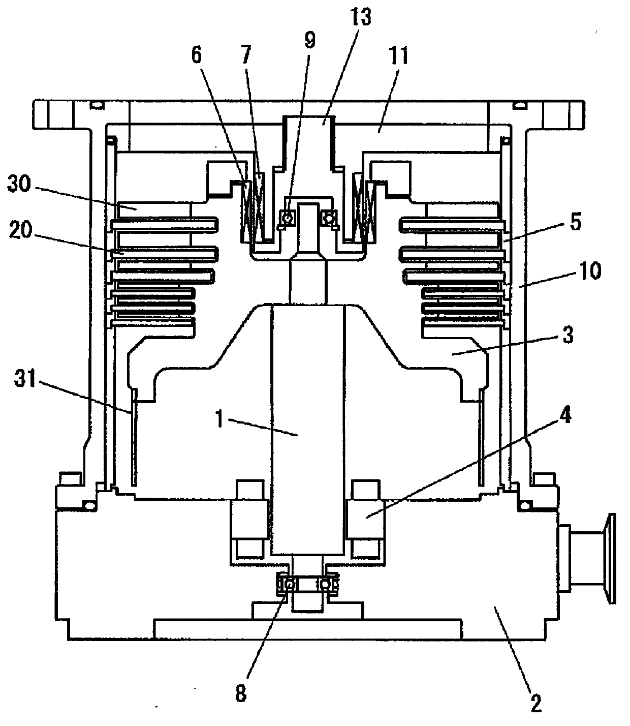
[0039] Hereinafter, embodiments for implementing the present invention will be described with reference to the drawings. figure 1 It is a figure which shows one embodiment of the vacuum pump of this invention, and is a cross-sectional view of a turbomolecular pump. Rotary vanes 30 and a cylindrical portion 31 are formed in the rotor 3 as exhaust function portions. The fixed fins 20 are provided corresponding to the rotary fins 30 . In addition, a fixed cylinder as a fixed side exhaust function part is provided corresponding to the cylindrical part 31, but in figure 1 Illustrations are omitted.

[0040] The rotor 3 is fastened on the shaft 1 and the shaft 1 is driven in rotation by the electric motor 4 . The rotor 3 fastened to the shaft 1 is rotatably supported by using a magnetic bearing having permanent magnets 6 and 7 and a ball bearing 8 . For the ball bearing 8, for example, an angular contact ball bearing is used. A cylindrical permanent magnet 6 is fixed on the rot...


PUM


Abstract

The present invention provides a vacuum pump capable of suppressing the structure from becoming complicated and improving the damping effect. The vacuum pump includes: a holding mechanism for clamping an outer race of the ball bearing in an axial direction and holding the outer race so that the outer race moves along a radial direction; and an elastic member disposed at an outer circumferential side of the outer race. The elastic member is disposed in contact with or close to the outer circumferential side of the outer race. Oil or grease is injected into a gap between the elastic member and the outer race. Through holding the outer race against the elastic member, the elastic member is deformed to suppress vibration. Furthermore, through injecting oil or grease into the gap, the damping effect can be further improved.

Description

technical field [0001] The present invention relates to a vacuum pump, in particular to a vacuum pump using ball bearings as bearings. Background technique [0002] The bearing mechanism of the turbomolecular pump includes a structure using only ball bearings, a structure using ball bearings and permanent magnets, and a magnetic bearing structure using only electromagnets. As a turbomolecular pump having a structure using ball bearings and permanent magnets, a structure described in Patent Document 1 is known. [0003] In general, the rotational frequency of the turbomolecular pump is higher than the resonance frequency (secondary critical speed) of the rotating body, so it is necessary to pass through the resonance frequency (secondary critical speed) when starting and stopping the pump. The rotating body vibrates when passing the resonant frequency, but in the case of bearings using electromagnets, the vibration of the rotating shaft can be actively controlled. However, ...

Claims


Application Information

Patent Timeline
Patent Type & Authority Applications(China)
IPC IPC(8): F04D29/059F04D29/05F04D19/04
CPCF04D29/644F04D19/04F04D19/042F04D29/063F04D29/059F04D29/05F04D29/668F16C19/06F16C27/045F16C27/066F16C2360/45
Inventor 关田幸照
Owner SHIMADZU SEISAKUSHO CO LTD
Why Eureka
Try Eureka