
Period reciprocating magnetic edgy current shaft coupling

A magnetic eddy current and coupling technology, applied in the direction of asynchronous inductive clutch/brake, etc., can solve the problems of difficult to apply load, consume a lot of manpower, waste of manpower, etc., achieve stable and reliable performance, simple structure, save energy and manpower Effect

Active Publication Date: 2015-04-15
芜湖铭信电机节能科技有限公司
View PDF3 Cites 0 Cited by
  • Summary
  • Abstract
  • Description
  • Claims
  • Application Information

AI Technical Summary

Problems solved by technology

[0004] For loads that work periodically and intermittently (the so-called loads that work intermittently refer to kowtow machines, which need to be powered to work for a period of time in each work cycle, and do not need to be powered for another period of time. To provide power, the power supply needs to be disconnected to save energy), the mature coupling technology on the market at present, whether it is the traditional rigid coupling or the existing magnetic eddy current coupling, due to the structure and technology of the product itself Due to the limitations of the solution, there are still many deficiencies in the technical performance of the product itself that need to be improved, mainly as follows: ① In order to disconnect the power supply, the traditional rigid coupling needs to turn off and start the motor frequently, which is easy to cause waste of manpower and damage to the motor. ②In order to perform periodic air gap adjustment, the chute of the ordinary magnetic eddy current coupling is not closed due to the air gap adjustment mechanism. When the slider of the air gap adjustment mechanism reaches the end of the chute, manual labor is required every working cycle It takes a lot of manpower to control the reverse rotation of the motor of the air gap drive mechanism. In addition, under this technical solution, it may be necessary to detect the position sensor of the cam to confirm whether the cam has reached the end of the chute
These technical shortcomings and deficiencies make it difficult for the current coupling to be suitable for periodic intermittent work loads such as kowtow machines

Method used


Image

  • Period reciprocating magnetic edgy current shaft coupling
  • Period reciprocating magnetic edgy current shaft coupling
  • Period reciprocating magnetic edgy current shaft coupling

Examples


Embodiment Construction

[0026] The present invention will be further described below with reference to the accompanying drawings.

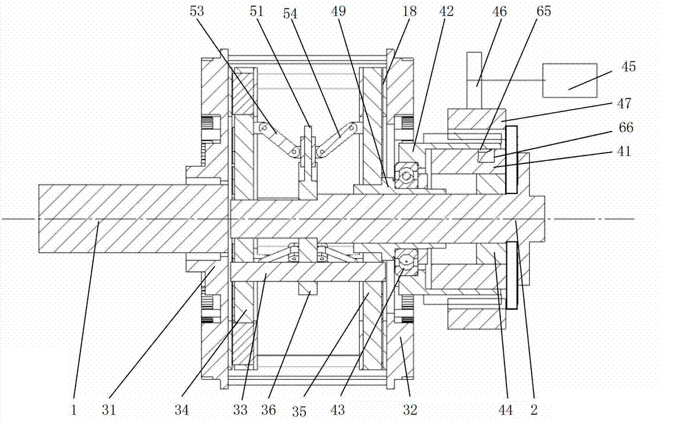
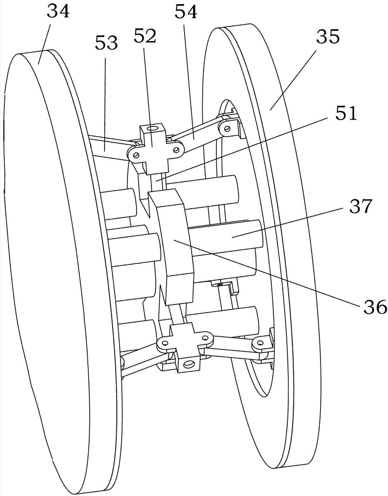
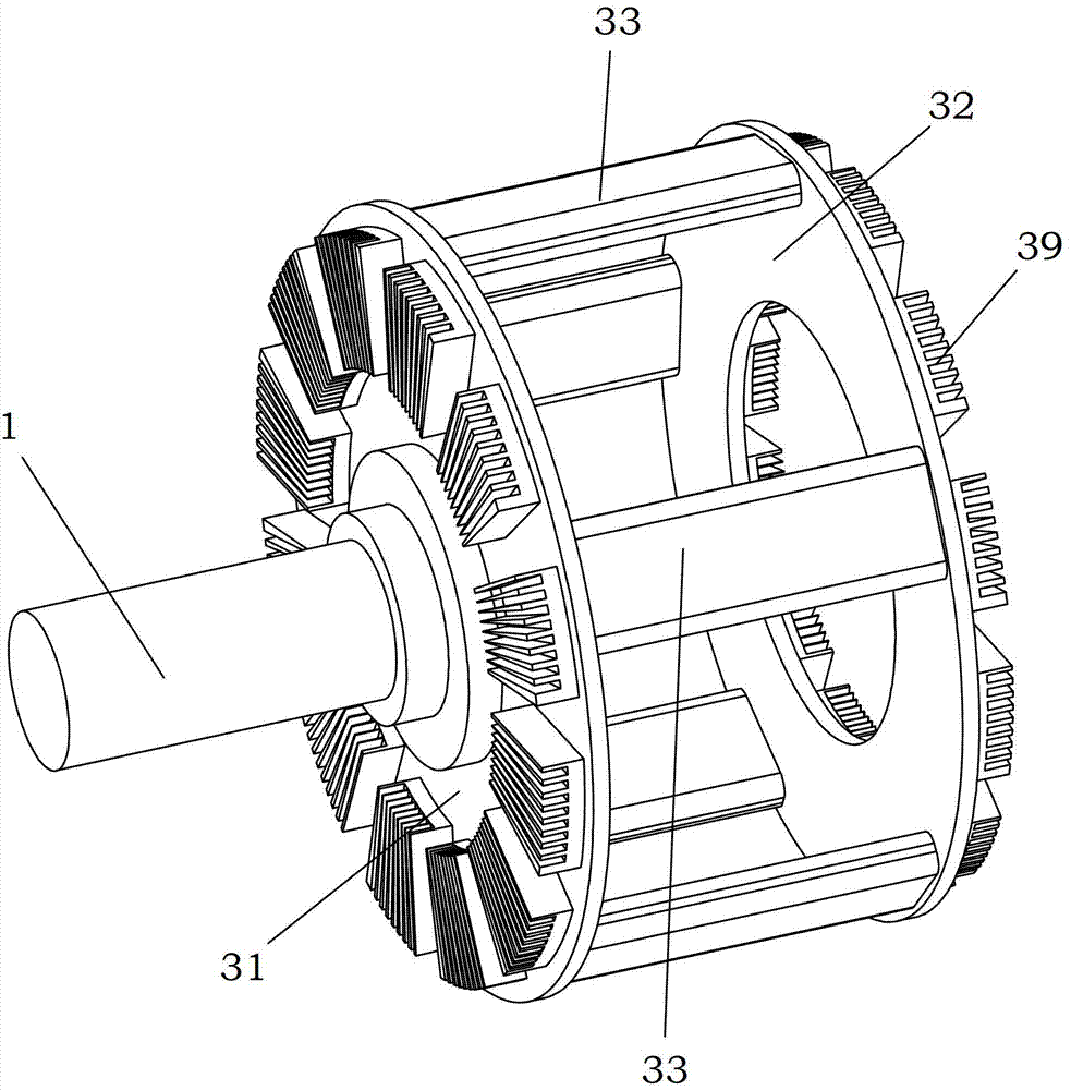
[0027] refer to Figure 1-5: Periodic reciprocating magnetic eddy current coupling, comprising an input shaft 1 connected to the first motor and an output shaft 2 connected to the load, the input shaft 1 is fixedly fitted with a left conductor disc 31, the magnetic eddy current coupling It also includes a right conductor disk 32 arranged in parallel with the left conductor disk 31, and the right conductor disk 32 rotates synchronously with the left conductor disk 31 through a connector 33. In this embodiment, the connector 33 is a plurality of steel plates, and the left conductor disk 31, A cage structure is formed between the steel plate and the right conductor disk 32, a left disk 34 and a right disk 35 are arranged between the left conductor disk 31 and the right conductor disk 32, and an output shaft is arranged between the left disk 34 and the right disk 35. 2 The ...


PUM


Abstract

The invention relates to a period reciprocating magnetic edgy current shaft coupling. The period reciprocating magnetic edgy current shaft coupling comprises an input shaft which is connected with a first motor, and an output shaft which is connected with load. A left conductor disc is fixedly sleeved on the input shaft. The period reciprocating magnetic edgy current shaft coupling further comprises a right conductor disc which is in parallel with the left conductor disc. The right conductor and the left conductor disc rotate synchronously. A left magnetic disc and a right magnetic disc are arranged between the left conductor disc and the right conductor disc. A middle disc which is fixedly connected with the output shaft is arranged between the left magnetic disc and the right magnetic disc. The left magnetic disc, the middle disc, the right magnetic disc, and the left conductor disc are arranged in a parallel mode. The left magnetic disc, the middle disc, and the right magnetic disc rotate synchronously. The period reciprocating magnetic edgy current shaft coupling further comprises an air gap space regulating mechanism. The period reciprocating magnetic edgy current shaft coupling has the advantages of being suitable for connecting load which needs to work in a periodic and intermittent mode, when the load is in working clearance, the shaft coupling enables the load to be disconnected with the motor, people do not need to frequently turn off or turn on the motor, and energy and manpower are saved.

Description

technical field [0001] The invention relates to a magnetic eddy current coupling. Background technique [0002] In real life, the drive shaft transmission system connected by a coupling is widely used. Almost industrial occasions and areas involving motor power transmission in life will use the drive shaft transmission technology of the coupling. At present, the couplings used in the mechanical field are mostly mechanical couplings and hydraulic couplings. The mechanical coupling is a rigid connection, and the mechanical force transmits the torque. During the installation process, due to the axial offset error, the load of the supporting original will be increased, and the radial offset error will produce a sudden change load and cause high equipment In addition, the rigid connection will also generate impact load at the moment of starting. The speed regulation of the hydraulic coupler is an inefficient speed regulation method, the speed regulation range is limited, the hi...

Claims


Application Information

Patent Timeline
Patent Type & Authority Patents(China)
IPC IPC(8): H02K49/04
Inventor 甘春标袁海辉杨世锡池永为黄伟迪王威刘永强何俊
Owner 芜湖铭信电机节能科技有限公司
Learn More