Magnetic eddy-current coupler

A coupling and magnetic eddy current technology, applied in the direction of electrical components, electromechanical devices, electromechanical transmission devices, etc., can solve the problems of large performance impact, multiple mechanisms, unstable execution reliability, etc., to achieve stable and reliable performance, speed regulation The effect of high precision and simple structure

Inactive Publication Date: 2013-05-15
ZHEJIANG UNIV
View PDF5 Cites 0 Cited by
  • Summary
  • Abstract
  • Description
  • Claims
  • Application Information

AI Technical Summary

Problems solved by technology

However, due to the limitations of the product's own structure and technical solutions, there are still many deficiencies in the product's technical performance that need to be improved, mainly as follows: ① The coupling governor itself cannot automatically adjust the air gap spacing, and it needs to be equipped with related devices to realize the air gap spacing. Adjustment to complete the speed regulation function, the design of the corresponding actuator has a great influence on the performance of the product; ②The mechanical mechanism for adjusting the air gap spacing in the product has inherent technical requirements. For magnetic turntables that appear in pairs, the gap adjustment mechanism is mostly It has the characteristics of many mechanisms and unstable execution reliability. These characteristics affect the application of couplings in occasions with high requirements for speed regulation accuracy.

Method used


Image

  • Magnetic eddy-current coupler
  • Magnetic eddy-current coupler
  • Magnetic eddy-current coupler

Examples


Embodiment Construction

[0024] The present invention will be further described below in conjunction with accompanying drawing.

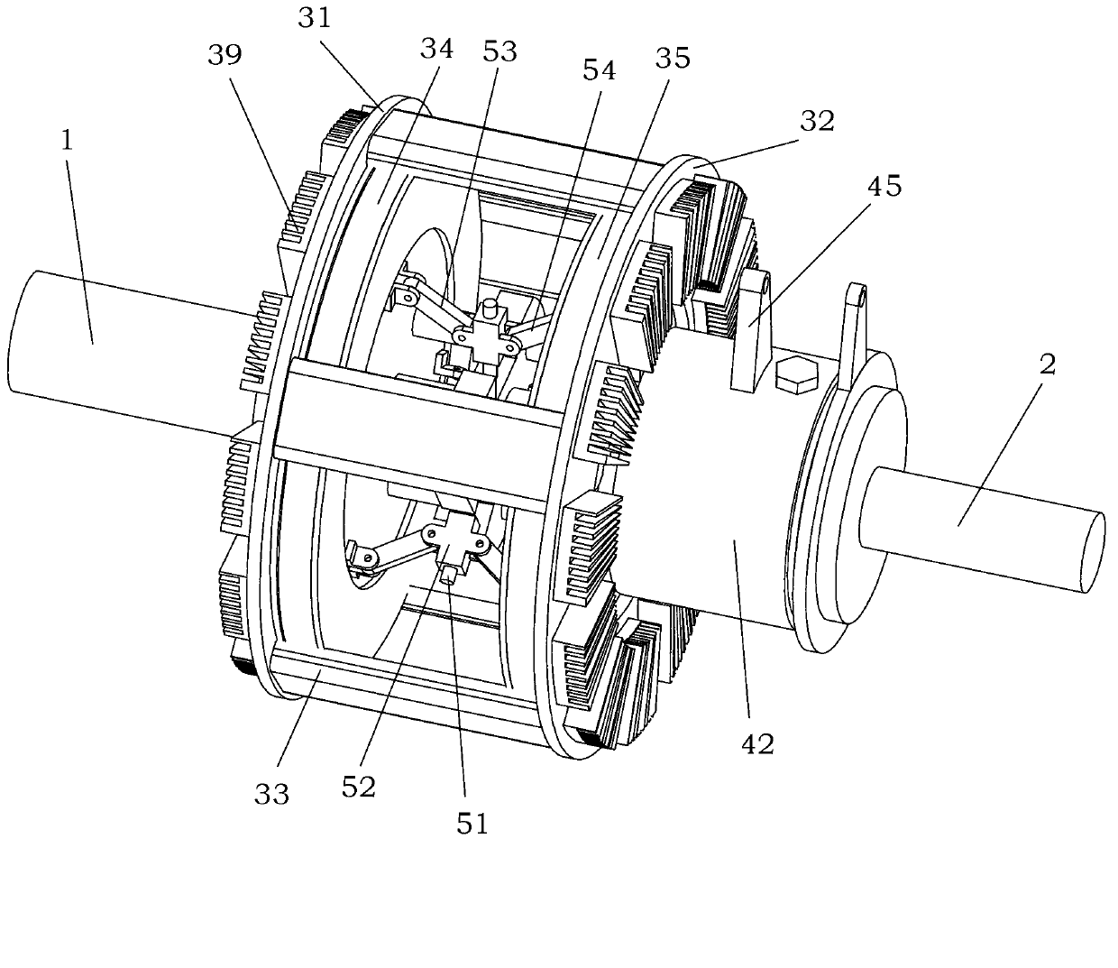
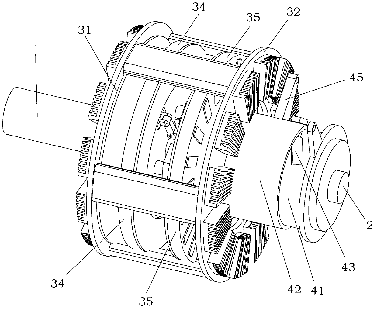
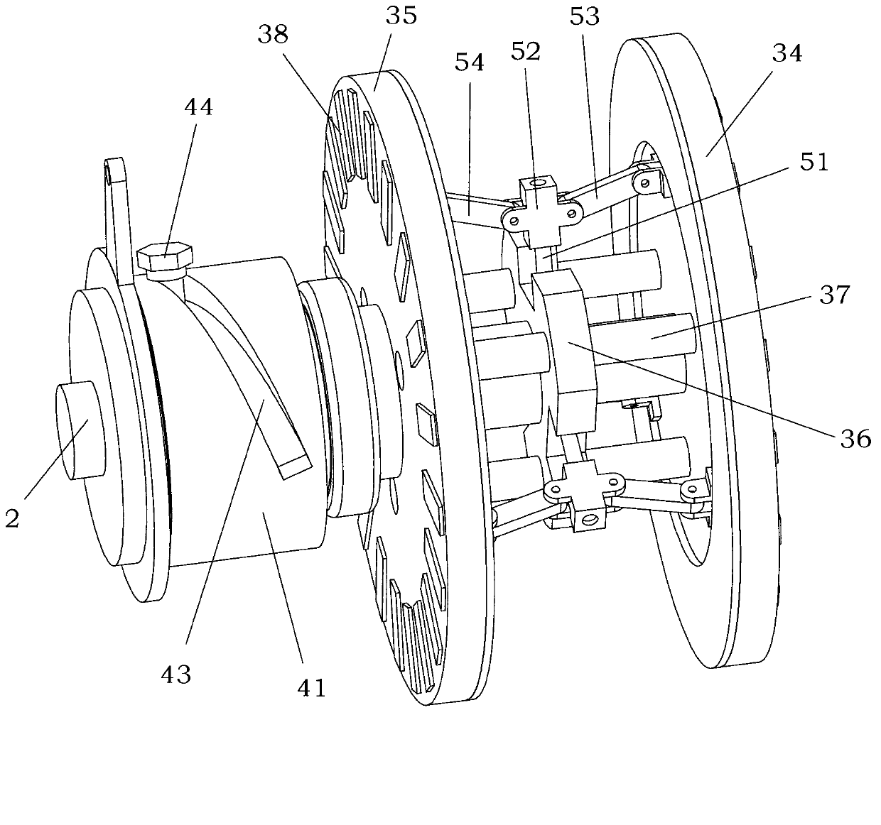
[0025] refer to Figure 1-5 : Magnetic eddy current coupling, including the input shaft 1 connected with the motor, the output shaft 2 connected with the load, the left conductor disc 31 is fixedly set on the input shaft 1, and the magnetic eddy current coupling also includes the left conductor The right conductor disk 32 arranged in parallel with the disk 31, the right conductor disk 32 rotates synchronously with the left conductor disk 31 through the connector 33, in the present embodiment, the connector 33 is a plurality of steel plates, the left conductor disk 31, the steel plate, the right conductor disk 32 to form a cage structure, a left magnetic disk 34 and a right magnetic disk 35 are arranged between the left conductive disk 31 and the right conductive disk 32, and a middle disk fixedly connected to the output shaft 2 is arranged between the left magnetic disk 34 ...


PUM


Abstract

The invention relates to a magnetic eddy-current coupler which comprises an input shaft which is connected with a motor and an output shaft which is connected with load. The input shaft is fixedly sleeved with a left conductor plate. The magnetic eddy-current coupler further comprises a right conductor plate which is arranged with the left conductor plate in a parallel mode. The right conductor plate synchronously rotates with the left conductor plate through a connecting piece. A left magnetic plate and a right magnetic plate are arranged between the left conductor plate and the right conductor plate. A middle plate which is fixedly connected with the output shaft is arranged between the left magnetic plate and the right magnetic plate. The left magnetic plate, the middle plate and the right magnetic plate are arranged with the left conductor plate in a parallel mode. The left magnetic plate, the middle plate and the right magnetic plate synchronously rotate. The magnetic eddy-current coupler further comprises an air gap space adjusting machine which is capable of adjusting an air gap space between the left conductor plate and the left magnetic plate and an air gap space between the right conductor plate and the right magnetic plate. The magnetic eddy-current coupler is stable, reliable and efficient, is provided with the air gap space adjusting machine and is capable of conveniently achieving speed increasing or reducing requirements in a working condition process.

Description

technical field [0001] The invention relates to a magnetic eddy current coupling. Background technique [0002] In real life, the drive shaft transmission system connected by a coupling is widely used. Almost industrial occasions and areas involving motor power transmission in life will use the drive shaft transmission technology of the coupling. At present, the couplings used in the mechanical field are mostly mechanical couplings and hydraulic couplings. The mechanical coupling is a rigid connection, and the mechanical force transmits the torque. During the installation process, due to the axial offset error, the load of the supporting original will be increased, and the radial offset error will produce a sudden change load and cause high equipment In addition, the rigid connection will also generate impact load at the moment of starting. The hydraulic coupler speed regulation is an inefficient speed regulation method, the speed regulation range is limited, the high-spee...

Claims


Application Information

Patent Timeline
IPC IPC(8): H02K51/00
Inventor 甘春标王威杨世锡池永为袁海辉黄伟迪刘永强何俊
Owner ZHEJIANG UNIV
Why Eureka
Try Eureka