A relative flux sensor and a method of determining a ratio between maximum light intensities, a control device, a color tunable lamp, a luminaire and a computer program product

A luminous flux sensor and luminous flux technology, applied in lighting devices, electroluminescent light sources, light sources, etc., can solve problems such as expensive methods and systems

Inactive Publication Date: 2013-05-15
KONINKLIJKE PHILIPS ELECTRONICS NV
View PDF4 Cites 5 Cited by
  • Summary
  • Abstract
  • Description
  • Claims
  • Application Information

AI Technical Summary

Problems solved by technology

Therefore, the methods and systems of the cited patent application are too expensive to be used to characterize illuminants of lighting systems

Method used


Image

  • A relative flux sensor and a method of determining a ratio between maximum light intensities, a control device, a color tunable lamp, a luminaire and a computer program product
  • A relative flux sensor and a method of determining a ratio between maximum light intensities, a control device, a color tunable lamp, a luminaire and a computer program product
  • A relative flux sensor and a method of determining a ratio between maximum light intensities, a control device, a color tunable lamp, a luminaire and a computer program product

Examples


Embodiment Construction

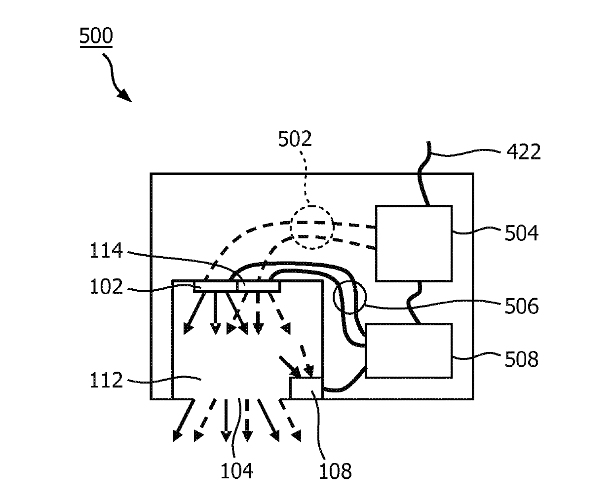
[0071] The first embodiment is shown in figure 1 . A light source 101 is shown comprising a first light emitting diode (LED) 102 and a second LED 114 . The first LED 102 emits light of a first color into the light mixing cavity 112 of the light source 101 . The second LED 114 emits light of a second color into the light mixing cavity 112 . The second color is different from the first color. The light mixing cavity 112 includes a light exit window 104 . Light that is a mixture of the first color and the second color is emitted through the light exit window 104 into the environment of the light source 101 .

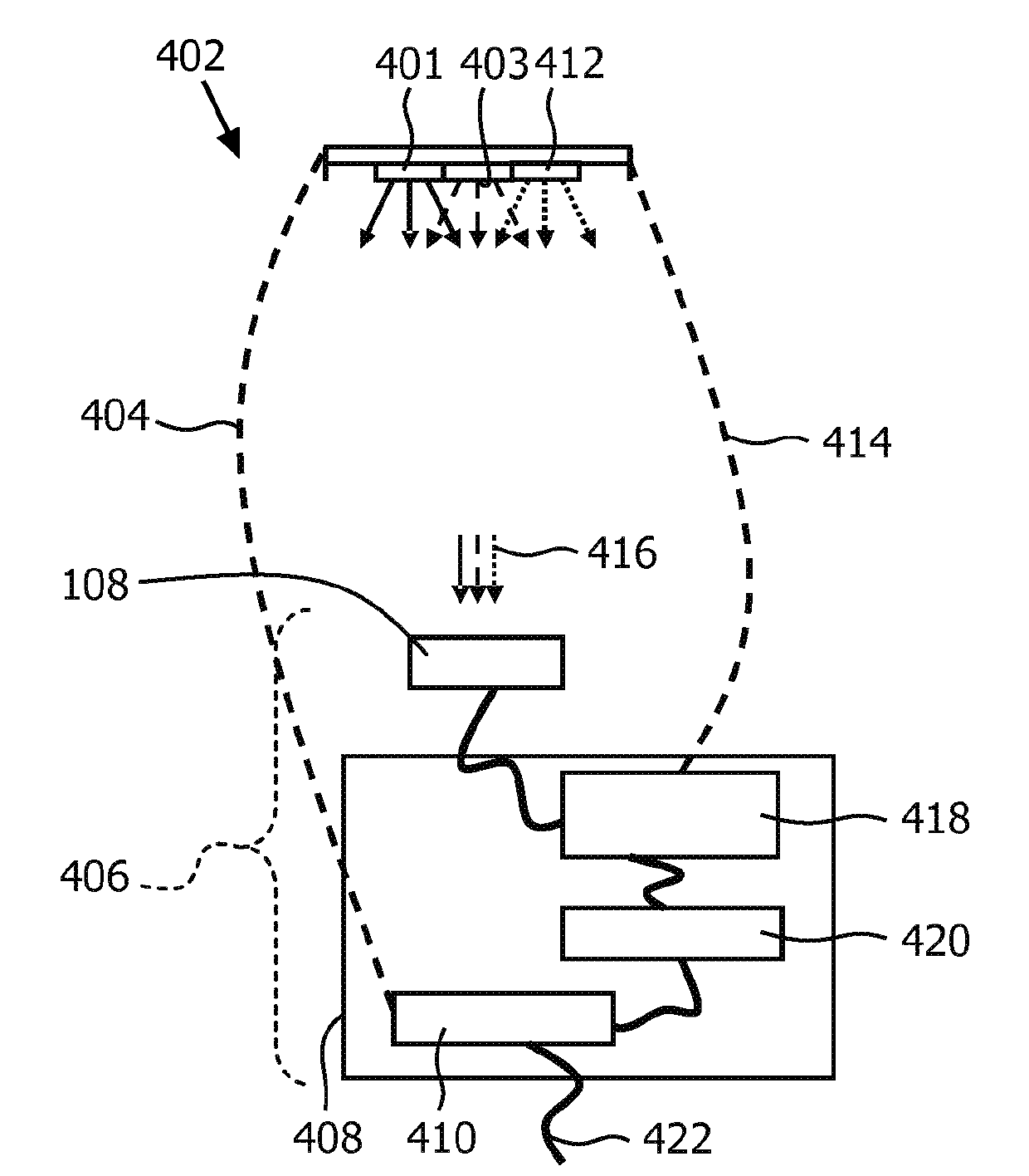
[0072] A relative light flux sensor 122 is also shown. The relative light flux sensor 122 includes a light input 106 through which light can enter the relative light flux sensor 122 to impinge on the color point sensor 108 . Color point sensor 108 is coupled to sensor controller 118 of relative light flux sensor 122 . The sensor controller 118 is coupled to an output...


PUM


Abstract

A relative flux sensor (122) and a method of characterizing characteristics of light emitters are provided. The relative flux sensor (122) comprises a color point sensor(108) and a sensor color (118). The color point sensor (108) measures a color point in a color space of light emitted by a light source (101) comprising a first light emitter (102) for emitting light of a first color and a second light emitter (114) for emitting light of a second color being different from the first color. The light source (101) is arranged for emitting light of a controllable color,being a mix of light of the first color and light of the second color.; The sensor controller (118) is coupled to the color point sensor (108) for receiving a measuring signal and is arranged for i)providing a first signal to the light source (101), the first signal comprising a dimming factor D1 and a dimming factor D2, the dimming factor D1 and the dimming factor D2 indicating a fraction of a maximum flux of the first light emitter(102) and the second light emitter (114), respectively, and receiving the measuring signal representing a first color point when the light source (101) emits light according to the first signal, wherein at least one of the dimming factors D1 and D2 is different from 0, ii) providing a second signal to the light source (101), the second signal comprising a dimming factor D4 and a dimming factor D5, the dimming factor D4 and the dimming factor D indicating a fraction of the maximum flux of the first light emitter (102); and the second light emitter (114), respectively, and receiving the measuring signal representing a second color point when the light source (101) emits light according to the second signal, wherein both dimming factors D4 and D5 are different from 0, iii) calculating within a model of the color 20 space a ratio between a maximum flux of the first light emitter (102) and a maximum flux of the second light emitter (114) on the basis of the first color point, the second color point, the dimming factors D1, D2, D4 and D5.

Description

technical field [0001] The invention relates to the field of light flux sensors. Background technique [0002] In a color-tunable lamp, each color is formed by mixing the light of at least two luminaires, each of which emits light of a different color. The first light emitter emits light of eg a first color, which may be defined by a first color point (x1, y1) in a color space. The second light emitter emits light of eg a second color, which may be defined by a second color point (x2, y2) in the color space. The emission of a certain amount of light of the first color relative to the emission of a certain amount of light of the second color causes the emission of a certain mixed color defined by the third color point (x12, y12) which passes through the second color point. The straight line between the first color point and the second color point is located between the first color point and the second color point. By precisely controlling the ratio between the amount of li...

Claims


Application Information

Patent Timeline
Patent Type & Authority Applications(China)
IPC IPC(8): H05B33/08H05B44/00
CPCH05B33/0869H05B37/02H05B45/22H05B47/10
Inventor L.T.温肯维勒格J.J.A.麦科马克J.米尤森
Owner KONINKLIJKE PHILIPS ELECTRONICS NV
Why Eureka
Try Eureka