Jet type glue supply head

A technology of injection point and glue head, which is applied in the direction of coating and liquid coating device on the surface, can solve the problems of low displacement magnification of the amplification mechanism, change of colloid viscosity, and limitation of dispensing efficiency, so as to overcome the impact of firing pin and Nozzle distance control is difficult, high resonance operating frequency, and the effect of overcoming the inconvenience of installation

Active Publication Date: 2013-05-22
XIAMEN UNIV
View PDF7 Cites 17 Cited by
  • Summary
  • Abstract
  • Description
  • Claims
  • Application Information

AI Technical Summary

Problems solved by technology

This dispensing method has several disadvantages that are difficult to overcome: First, the distance between the contact dispensing valve and the component is very small during operation. If the positioning of the component or the substrate is slightly shifted or deformed, it is easy to make the Damage to the dispensing tip and the substrate or component
Secondly, in contact dispensing, the amount of dispensing is usually controlled according to the viscosity of the colloid by adjusting the distance between the dispensing valve and the substrate and the relative movement speed. However, during the working process, changes in temperature will cause changes in the viscosity of the colloid. As a result, the amount of dispensing cannot be well controlled
Third, due to the dispensing of the contact nature, it is easy to cause wire drawing between the dispensing valve and the components, causing unnecessary adhesion between the substrate and the components
Fourth, because the dispensing valve has to

Method used


Image

  • Jet type glue supply head
  • Jet type glue supply head
  • Jet type glue supply head

Examples


Embodiment Construction

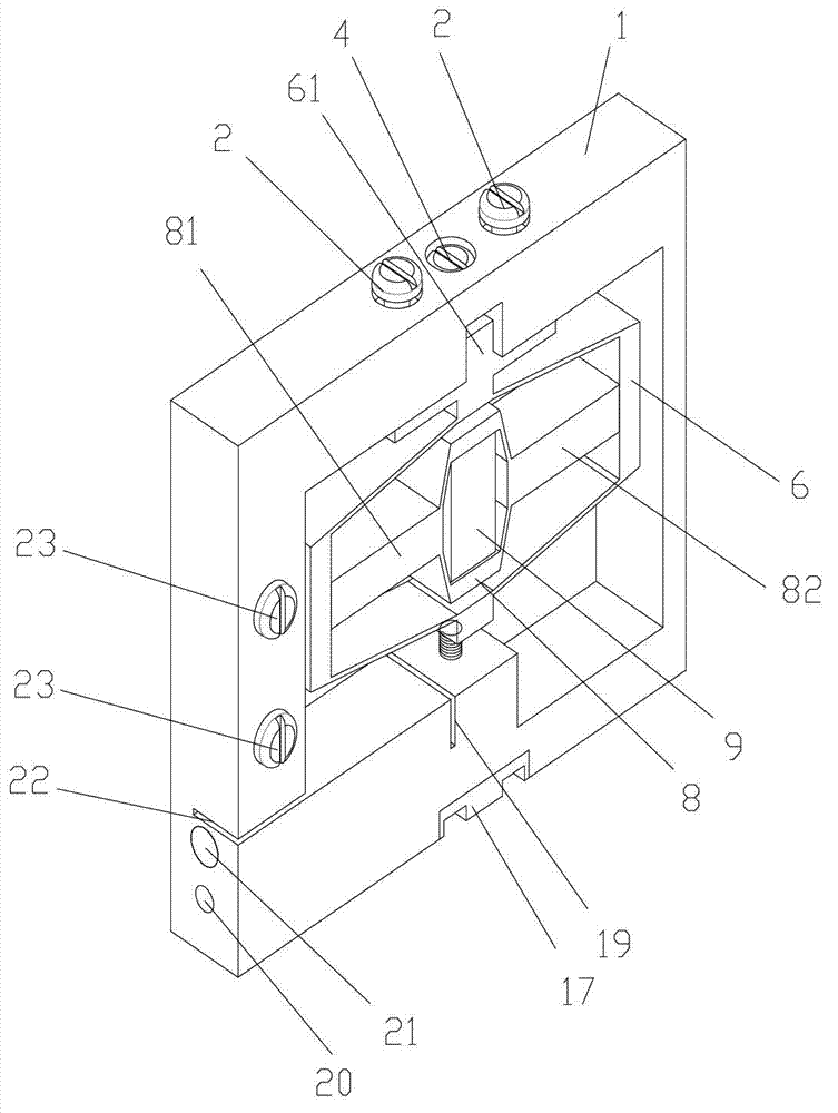
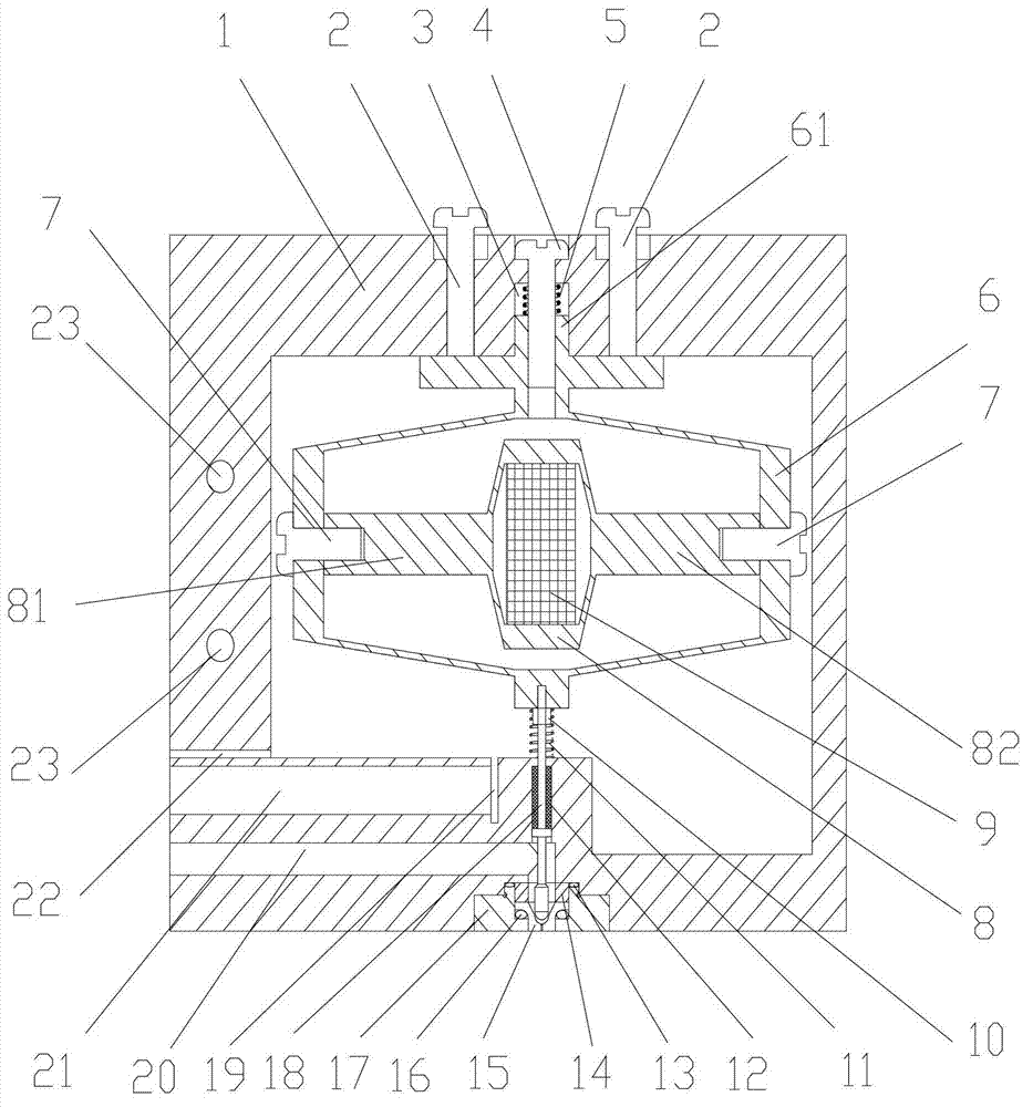
[0020] see figure 2 and 3 , The embodiment of the present invention includes a base 1, a heating block 21, a primary displacement amplifying mechanism, a secondary displacement amplifying mechanism, a striker 18, a striker return spring 11, a nozzle 15, a nozzle seat 17, and the like.

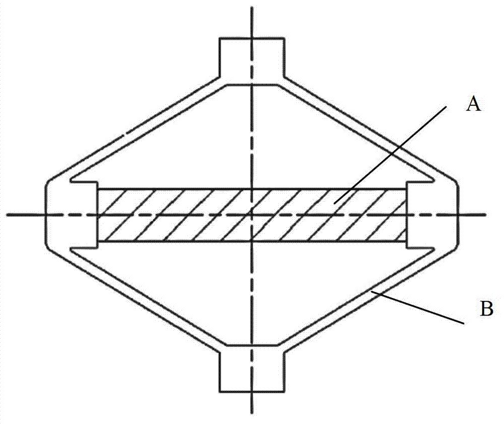
[0021] The base 1 is a planar rectangular frame, and the base 1 is provided with a colloid flow channel 20 . The heating block 21 is arranged in the base 1, and the heating block 21 is used to heat and adjust the temperature of the colloid flowing through the colloid channel 20 to the nozzle 15, so as to change the viscosity of the colloid, so as to be suitable for colloid injection with higher viscosity. The primary displacement amplification mechanism is provided with a planar inner diamond frame 8, a piezoelectric ceramic block 9, a left stretch arm 81 and a right stretch arm 82, and the left stretch arm 81, the right stretch arm 82 and the planar inner rhombus frame 8 The left and right ...


PUM


Abstract

The invention relates to a jet type glue supply head. The jet type glue supply head comprises a base, a heating block, a first grade displacement and amplification mechanism, a second grade displacement and amplification mechanism, a striker, a striker return spring, a nozzle, a nozzle holder and a piezoelectric ceramic block, wherein the base is provided with a gel channel, the heating block is arranged in the base, the first grade displacement and amplification mechanism is provided with a plane internal diamond frame, a right stretching arm and a left stretching arm, and the right stretching arm and the left stretching arm are symmetrically arranged on the right side and the left side of the plane internal diamond frame; the second grade displacement and amplification mechanism is provided with a plane external diamond frame, the left stretching arm and the right stretching arm are symmetrically and horizontally connected with the left and right sides of the plane external diamond frame, the upper end of the plane external diamond frame is connected with the upper part of the base, the striker is perpendicularly arranged, the upper end of the striker supports the lower end of the plane external diamond frame, and the lower part of the striker is positioned in the base; and the striker return spring is arranged between the lower end of the plane external diamond frame and the wall of the base, and is sheathed on the striker, the nozzle is arranged on the base by the nozzle holder, the nozzle is right positioned under the striker, a nozzle hole is communicated with the gel channel of the base, and the piezoelectric ceramic block is arranged in the plane internal diamond frame.

Description

technical field [0001] The invention relates to a fluid dispensing head, in particular to a jet dispensing head. Background technique [0002] Dispensing heads are commonly used equipment in electronic product processing and packaging. The dispensing methods of the existing fluid dispensing head are generally divided into contact type and non-contact type. The principle of the contact dispensing head is to push the fluid through needles of different apertures to contact the substrate and components with a certain air pressure for dispensing. This dispensing method has several disadvantages that are difficult to overcome: First, the distance between the contact dispensing valve and the component is very small during operation. If the positioning of the component or the substrate is slightly shifted or deformed, it is easy to make the Damage to the dispensing tip and substrate or component. Secondly, in contact dispensing, the amount of dispensing is usually controlled acco...

Claims


Application Information

Patent Timeline
IPC IPC(8): B05C5/04B05C11/10
Inventor 王凌云蔡建法李益盼何勇杜晓辉王小萍
Owner XIAMEN UNIV
Why Eureka
Try Eureka