
Multi-unmanned aerial vehicle patrol dispatching method based on optical fiber disturbance monitoring system

A technology of monitoring system and dispatching method, applied in control/regulation system, non-electric variable control, vehicle position/route/height control, etc. Insufficient human-machine battery life and other problems, to overcome the short battery life, reduce costs, and reduce the effect of construction difficulty

Inactive Publication Date: 2021-12-31
TIANJIN QIU SHI FIBER TECH
View PDF0 Cites 1 Cited by
  • Summary
  • Abstract
  • Description
  • Claims
  • Application Information

AI Technical Summary

Problems solved by technology

Although UAV patrols have many advantages, but limited by battery technology and wireless transmission technology, there are also many insurmountable shortcomings: First, the existing UAV battery life is obviously insufficient. drones, which only support 30km cruising range, are far from satisfactory for large-scale security systems (such as airports, military bases, etc.) or super-large security systems (borders, etc.) with a monitoring range of hundreds of kilometers; Most of them use 2.4G or 5.8G transmission. Even if the wireless module increases the power, it is controlled by the domestic electromagnetic environment and building shielding. 30km is the limit of image transmission, which cannot meet the needs of large or super large security systems; finally, even in small security systems Among them, controlled by the battery technology, the drone’s battery life is only 30-40 minutes, and it cannot be on duty around the clock
Based on the above problems, this is also the main reason why drone patrols cannot be widely used

Method used


Image

  • Multi-unmanned aerial vehicle patrol dispatching method based on optical fiber disturbance monitoring system
  • Multi-unmanned aerial vehicle patrol dispatching method based on optical fiber disturbance monitoring system
  • Multi-unmanned aerial vehicle patrol dispatching method based on optical fiber disturbance monitoring system

Examples


Embodiment Construction

[0019] In order to further understand the invention content, characteristics and effects of the present invention, the following examples are given, and detailed descriptions are as follows in conjunction with the accompanying drawings:

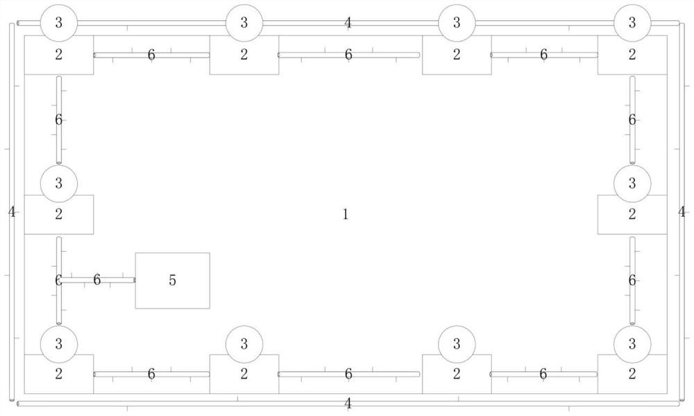
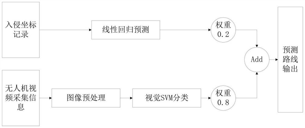
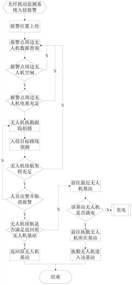
[0020] see Figure 1 ~ Figure 3 , a multi-UAV patrol scheduling method based on optical fiber disturbance monitoring system, adopts the following steps:

[0021] 1) According to the perimeter and area of ​​the monitoring area and the cruising range of the drone, calculate the required drones and complete the layout. Each drone is equipped with a drone base station, and the distance L between any two drone base stations must not exceed one The maximum cruising range S of the UAV, each UAV base station is equipped with a wireless data receiving module, a network data wired transmission module and a UAV wireless charging module. Taking into account factors such as weather, wind speed, drone battery attenuation, L should not be greater than 90% ...


PUM


Abstract

The invention discloses a multi-unmanned aerial vehicle patrol dispatching method based on an optical fiber disturbance monitoring system. The method comprises the following steps: 1) unmanned aerial vehicles and unmanned aerial vehicle base stations are arranged; 2) when an intrusion behavior occurs in the monitoring area, the optical fiber disturbance monitoring system gives an alarm and uploads the alarm data to an optical fiber unmanned aerial vehicle dispatching system; 3) the optical fiber unmanned aerial vehicle dispatching system arranges the unmanned aerial vehicles to go to the scene for on-duty, tracking and shooting according to the position of the alarm point; 4) the on-duty unmanned aerial vehicle returns data to the optical fiber unmanned aerial vehicle dispatching system; 5) the optical fiber unmanned aerial vehicle dispatching system completes prediction of a future intrusion advancing route and outputs the predicted route to the next level; (6) the optical fiber unmanned aerial vehicle dispatching system dispatches the unmanned aerial vehicles to relay on duty until the on-duty personnel go out of police and the unmanned aerial vehicle dispatching system cancels the alarm; and 7) the homeward flight unmanned aerial vehicles are charged for standby. All-weather on-duty of the unmanned aerial vehicles can be achieved, construction is easy and convenient, and the input cost is low.

Description

technical field [0001] The invention belongs to the field of unmanned aerial vehicle security, and in particular relates to a multi-unmanned aerial vehicle patrol scheduling method based on an optical fiber disturbance monitoring system. Background technique [0002] With the continuous improvement of the global economic level, people's quality of life has changed a lot. People pay more and more attention to material property and life safety, and the demand for security is also getting higher and higher. At the same time, the country's infrastructure is becoming more and more complete, such as schools, airports, gas stations, military bases, etc. have increased significantly. However, the development of science and technology is also easy to cause lawbreakers to use higher-level technology to illegally invade, steal public property and even harm people's lives, which seriously interferes with people's lives and destroys social stability. It is a huge challenge for security w...

Claims


Application Information

Patent Timeline
Patent Type & Authority Applications(China)
IPC IPC(8): G05D1/10
CPCG05D1/101
Inventor 刘柯
Owner TIANJIN QIU SHI FIBER TECH
Learn More