Steel cage rolling welding traction device

A traction device, reinforcement cage technology, used in welding equipment, resistance welding equipment, metal processing equipment, etc.

Inactive Publication Date: 2015-08-12
江苏固丰管桩集团有限公司
View PDF7 Cites 0 Cited by
  • Summary
  • Abstract
  • Description
  • Claims
  • Application Information

AI Technical Summary

Problems solved by technology

[0005] In view of the above problems, the main purpose of the present invention is to provide a traction device for steel cage roll welding, which solves the problem of deflection from the heavy steel cage, so as to ensure the quality of roll welding

Method used


Image

  • Steel cage rolling welding traction device

Examples


Embodiment Construction

[0019] The technical scheme of the present invention is further described below in conjunction with embodiment and accompanying drawing, but not as its limitation:

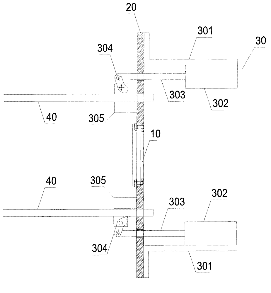
[0020] Such as figure 1 As shown, the traction device for steel cage roll welding provided by the present invention includes a traction trolley, a traction main shaft 10, a traction plate 20, and a locking assembly 30, wherein:

[0021] The traction trolley is connected with the traction main shaft 10;

[0022] The traction plate 20 is fixed on both ends of the traction main shaft 10 through fixing elements;

[0023] The locking assembly 30 includes a cylinder bracket 301, a locking cylinder 302, a cylinder rod 303, an eccentric wheel 304, and a locking support 305, and the cylinder support 301 and the locking support 302 are respectively fixed on both sides of the traction plate 20. , the locking support 302 is provided with a groove; the locking cylinder 302 is fixed on the cylinder bracket 301, one end of the...


PUM


Abstract

The invention belongs to the field of building devices, and provides a steel reinforcement cage roll welding draw gear which comprises a draw trolley, a draw main shaft, draw plates and locking assemblies. The draw trolley is connected with the draw main shaft, and the draw plates are fixed at two ends of the draw main shaft through fixed elements. Each locking assembly comprises cylinder supports, locking cylinders, cylinder pull rods, eccentric wheels and locking supporting seats. The cylinder supports and the locking supporting seats are respectively fixedly arranged on two faces of the draw plates, and grooves are arranged in the locking supporting seats. The locking cylinders are fixedly arranged on the cylinder supports, and one ends of the cylinder pull rods are connected with the locking cylinders. The other ends of the cylinder pull rods penetrate through the draw plates, and in pivot connection with one ends of the eccentric wheels. The other ends of the eccentric wheels are connected in the grooves of the locking supporting seats in a pivoted mode through pin shafts. The steel reinforcement cage roll welding draw gear solves the problem of deflection of self-weight steel reinforcement cage so as to guarantee roll-welding quality, and meanwhile is suitable for roll welding of steel reinforcement cages in different specifications.

Description

technical field [0001] The invention belongs to the field of construction equipment, and in particular relates to a pulling device for steel cage roll welding, which is suitable for pulling and moving the forming end when the steel cage roll welding is formed. Background technique [0002] Among cement concrete products, reinforced concrete members are widely used, and are formed by pouring concrete into a reinforcement cage composed of longitudinal main reinforcement and stirrups. According to the different components, the connection formation of the longitudinal main reinforcement and the stirrup is also different. At present, there are two commonly used connection forms, one is that the formed stirrup is artificially bound with the longitudinal main reinforcement to form a reinforcement cage; the other is by seam welding machine The spiral stirrup is welded to the longitudinal main reinforcement to form a reinforcement cage. [0003] Manually tying stirrups takes a long ...

Claims


Application Information

Patent Timeline
Patent Type & Authority Patents(China)
IPC IPC(8): B23K11/36
Inventor 朱克平张风臣汤永柳华文升朱加刚蔡同喜李伟
Owner 江苏固丰管桩集团有限公司
Why Eureka
Try Eureka