Stirred tank with baffle plates capable of reducing accumulating materials at tank bottom

A technology of mixing tank and tank bottom, which is applied in mixer accessories, dissolving, mixer and other directions, and can solve problems such as disadvantages

Inactive Publication Date: 2013-06-05
SHENYANG ALUMINIUM MAGNESIUM INSTITUTE
View PDF4 Cites 2 Cited by
  • Summary
  • Abstract
  • Description
  • Claims
  • Application Information

AI Technical Summary

Problems solved by technology

[0003] In order to solve the above technical problems, the present invention provides a stirring tank with a baffle plate for reducing the accumulatio

Method used


Image

  • Stirred tank with baffle plates capable of reducing accumulating materials at tank bottom
  • Stirred tank with baffle plates capable of reducing accumulating materials at tank bottom

Examples


Embodiment 1

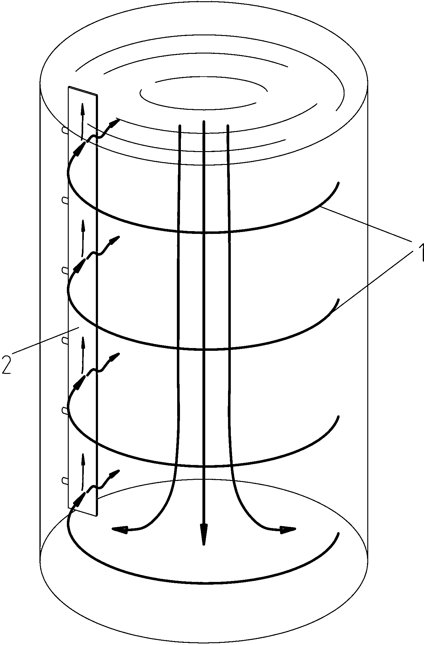
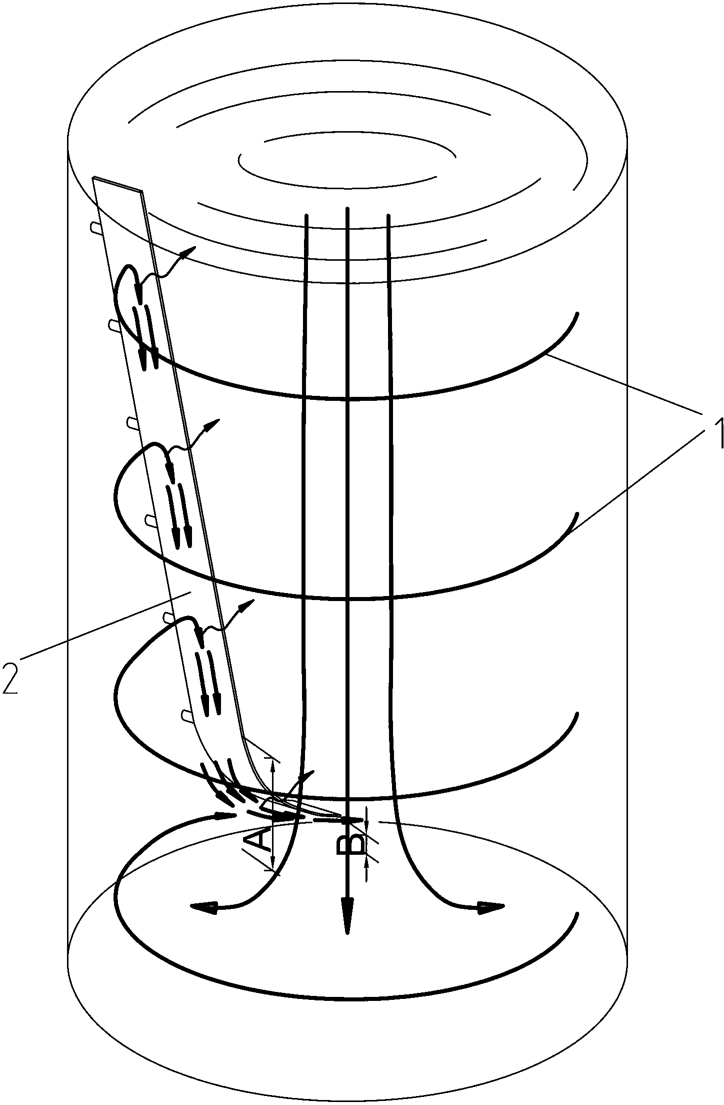
[0015] Such as figure 2 As shown, the present invention has a stirring tank with a baffle plate for reducing the accumulation at the bottom of the tank, including a tank body 1 and a baffle plate 2, and the straight plate shape of the middle and upper part of the baffle plate 2 is at an angle between 0-90 degrees with the axis of the tank body 1. In this embodiment, the included angle is 20 degrees. The lower part of the baffle plate 2 is arc-shaped and extends toward the bottom of the tank. The extending direction of the arc is consistent with the rotation direction of the feed liquid. The circumference is evenly distributed, the starting point of the arc at the lower part of the baffle 2 is A, and the end point is B; the distance between point A and the bottom of the groove is 1500-8000mm; the distance between point B and the bottom of the groove is 100-600mm, and the radius of the arc is 1000-8000mm. The tangent direction of the baffle is horizontal.

Embodiment 2

[0017] The middle and upper straight plate shape of the baffle plate 2 in the embodiment 1 forms an included angle of 3 degrees with the axis of the tank body 1 . Others are with embodiment 1.

Embodiment 3

[0019] The middle and upper straight plate shape of the baffle plate 2 in the embodiment 1 forms an angle of 85 degrees with the axis of the tank body 1 . Others are with embodiment 1.


PUM

PropertyMeasurementUnit
Radiusaaaaaaaaaa

Abstract

The invention relates to a stirring tank which is applied to all kinds of stirring tanks and stirring devices in the alumina industry, in particularly to a stirring tank with baffle plates capable of reducing accumulating materials at the tank bottom. The stirring tank with the baffle plates capable of reducing the accumulating materials at the tank bottom comprises a tank body and the baffle plates, and is characterized in that included angles between straight panel at the middle upper portion of the baffle plates and the axial line of the tank body are between 0-90 degrees. The lower portions of the baffle plates are circular-arc-shaped and extend towards the bottom of the tank. The extending direction of the circular arcs is consistent with the rotating direction of material solution, and is concave downwards. The baffle plates are evenly distributed inside the tank body along the circumference. The stirring tank with the baffle plates capable of reducing the accumulating materials at the tank bottom can effectively strengthen solution flow speed and impact force on the bottom corners of the tank, and obviously reduce stirring power of the stirring tank and the phenomena of sedimentary accumulating materials and scabbing at the tank bottom.

Description

technical field [0001] The invention relates to a stirring tank, which is suitable for stirring devices of various stirring tanks in the alumina industry, in particular to a stirring tank with a baffle plate for reducing accumulation at the bottom of the tank. It can effectively enhance the liquid flow rate and impact force at the corners of the bottom of the tank, and significantly reduce the sedimentation and scarring at the bottom of the tank. Background technique [0002] At present, in the production process of alumina hydrometallurgy, paddle-type stirring devices and traditional straight-plate baffles are often used in the stirring tank. The function of the straight baffle is to eliminate the cylindrical turning zone and increase the mixing effect. However, the traditional straight baffle is not conducive to eliminating the accumulation of material at the bottom of the tank. Because the straight plate baffle can eliminate the cylindrical turning zone and increase th...

Claims


Application Information

Patent Timeline
IPC IPC(8): B01F15/00
Inventor 张超李志国
Owner SHENYANG ALUMINIUM MAGNESIUM INSTITUTE
Why Eureka
Try Eureka