Upper sliding block suppressing force display mechanism of powder make-up machine

A technology of powder molding machine and display mechanism, which is applied in the field of powder metallurgy, can solve the problems of loss, inability to adjust the size of the pressing force, and easily damaged mechanisms, and achieve the effects of preventing jamming, facilitating timely adjustment, and facilitating reverse driving

Inactive Publication Date: 2013-06-05
YANGZHOU HAILI PRECISION MACHINERY MFG
View PDF0 Cites 1 Cited by
  • Summary
  • Abstract
  • Description
  • Claims
  • Application Information

AI Technical Summary

Problems solved by technology

[0002] The upper slider pressing mechanism is an important part of powder metallurgy, and its quality directly affects the quality of molded products. The existing upper slider pressing mechanism has the following defects: it cannot reflect the downward pressing force of the upper die, and cannot know The change of the pressing force in the mold cavity cannot timely adjust the size of the pressing force according to the actual situation of the product, which affects the molding quality of the product; and when the upper die is stuck in the female die, due to the existence of the upper pressing force, it is difficult to Difficult to turn the car back to make the upper die punch out of the female die, and the forced out is easy to damage the mechanism and cause losses

Method used


Image

  • Upper sliding block suppressing force display mechanism of powder make-up machine
  • Upper sliding block suppressing force display mechanism of powder make-up machine

Examples


Embodiment Construction

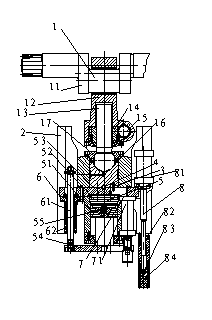
[0014] Below in conjunction with accompanying drawing, the present invention is described in further detail in conjunction with whole mechanism:

[0015] 1. Upper slider ball head screw adjustment mechanism 1:

[0016] This mechanism: (1) is used to adjust the pressurization amount of the upper die punch during pressing, that is, adjust the upper slider mechanism including the upper slider 2; (2) drive the upper slider connecting rod 12 by the transmission crankshaft 11, Complete the pressing and pressing process of the upper slider 2; (3) The closing height of the machine can be adjusted by adjusting the mechanism when the machine is assembled. Head anti-rotation ring 16 stops rotation, makes it can only move up and down under the drive of worm gear 14, thereby drives upper slider mechanism to move up and down by ball head changing plate 17, finishes adjustment process.

[0017] 2. Hydraulic cushion pressure display mechanism 5:

[0018] This mechanism monitors the working ...


PUM


Abstract

The invention relates to an upper sliding block suppressing force display mechanism of a powder make-up machine. The upper sliding block suppressing force display mechanism of the powder make-up machine is characterized by being arranged between an upper sliding block air cylinder plate and an upper connecting plate, comprising a hydraulic die cushion oil cylinder piston which is arranged on the lower portion of the upper sliding block air cylinder plate and a hydraulic die cushion oil chamber which is formed between the upper sliding block air cylinder plate and the hydraulic die cushion oil cylinder piston, and an upper air cylinder piston which is arranged on the lower portion of the hydraulic die cushion oil cylinder piston and connected with the upper connecting plate; and an upper air cylinder crash pad which is connected with the lower portion of the upper air cylinder piston is arranged on the lower portion of the upper air cylinder piston. The upper sliding block suppressing force display mechanism of the powder make-up machine adds a hydraulic die cushion pressure display mechanism which does not exist before, or is arranged on the lower position of a ball bowl piston, what is reflected is multiple aspect synthetic suppressing forces, after improvement, a placing position of the suppressing force display mechanism can authentically reflect the variable condition of die cavity suppressing force, namely real-time suppressing force is displayed, and so that timely adjustment by operating staff is convenient. In the meantime, the upper sliding block suppressing force display mechanism of the powder make-up machine can prevent a snap gauge from turning in a smothering mode and is convenient to turn reversely.

Description

technical field [0001] The invention relates to a sliding block pressing force display mechanism on a powder molding machine, which belongs to the technical field of powder metallurgy. Background technique [0002] The upper slider pressing mechanism is an important part of powder metallurgy, and its quality directly affects the quality of molded products. The existing upper slider pressing mechanism has the following defects: it cannot reflect the downward pressing force of the upper die, and cannot know The change of the pressing force in the mold cavity cannot timely adjust the size of the pressing force according to the actual situation of the product, which affects the molding quality of the product; and when the upper die is stuck in the female die, due to the existence of the upper pressing force, it is difficult to It is difficult to reverse the car to make the upper die punch out of the female die, and the forced out is easy to damage the mechanism and cause losses....

Claims


Application Information

Patent Timeline
IPC IPC(8): B22F3/03
Inventor 冯金玉潘学仁冯怿周
Owner YANGZHOU HAILI PRECISION MACHINERY MFG
Why Eureka
Try Eureka