
Support rod component

A support rod assembly and support rod technology, applied in mining equipment, mining equipment, earthwork drilling and mining, etc., can solve the problems of reducing the bearing capacity of the support, potential safety hazards of cables, and cumbersome replacement

Inactive Publication Date: 2013-06-05
STATE GRID CORP OF CHINA +1
View PDF8 Cites 3 Cited by
  • Summary
  • Abstract
  • Description
  • Claims
  • Application Information

AI Technical Summary

Problems solved by technology

[0002] In the prior art, there are a large number of supports in the tunnel, and many supports are not properly used due to the overload of cables placed in the later period or the drop-off of the embedded parts of the supports from the tunnel body due to the excessive instantaneous load during the installation of the joints during construction. Causes deformation, cracking and other load-bearing failures of the bracket, reduces the bearing capacity of the bracket, and brings great safety hazards to the operation of the cable. When replacing these brackets, the replacement is very cumbersome due to insufficient bearing capacity. Now There is no equipment in the existing technology that can provide extra bearing capacity for the bracket, and it is extremely difficult to restore the bracket to its original shape

Method used


Image

  • Support rod component
  • Support rod component
  • Support rod component

Examples


Embodiment Construction

[0023] It should be noted that, in the case of no conflict, the embodiments in the present application and the features in the embodiments can be combined with each other. The present invention will be described in detail below with reference to the accompanying drawings and examples.

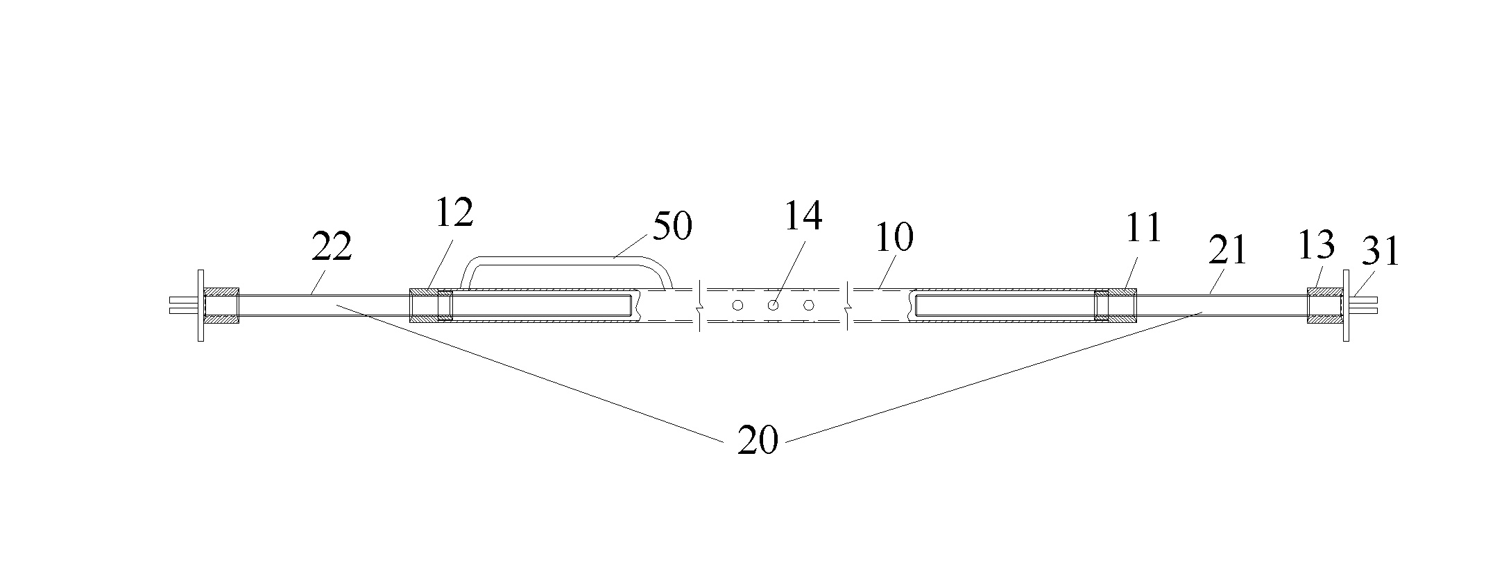
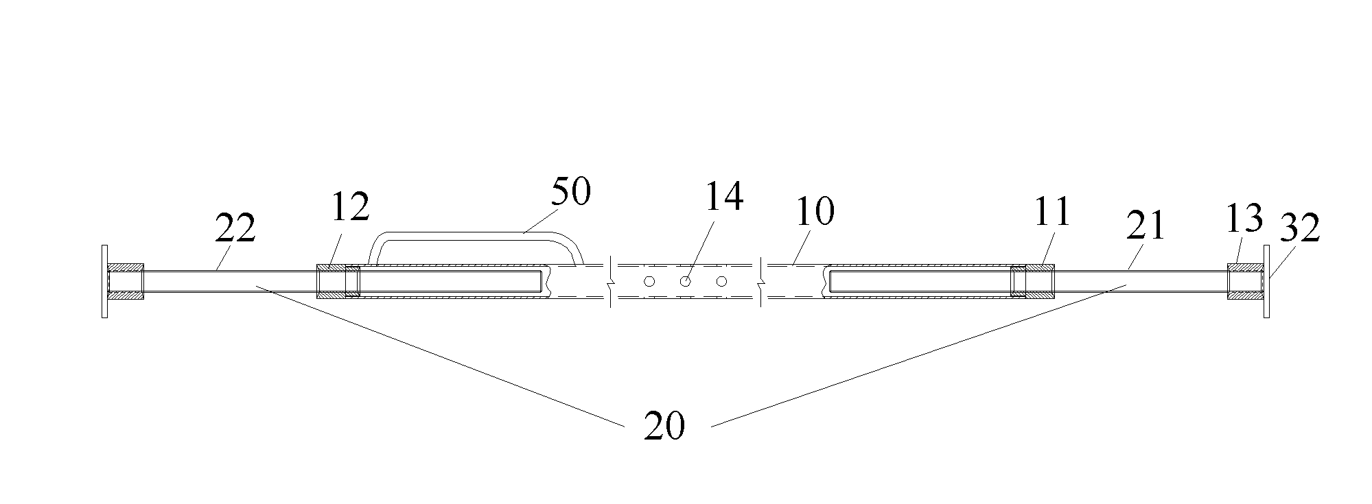
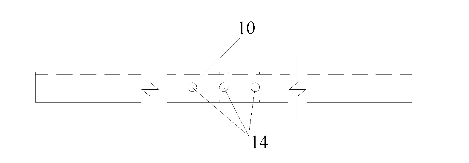
[0024] figure 1 A schematic diagram of Embodiment 1 of the support rod assembly according to the present invention is shown. As shown in the figure, the support rod assembly in this embodiment includes: a main pipe 10 and a support rod 20, and the support rod 20 is telescopically arranged on the main pipe 10 the end of. The support rod assembly of this embodiment adjusts the position of the support rod 20 in the main pipe 10, and then adjusts the length of the support rod assembly, so that the support rod assembly can adapt to different supports or tunnels, and the support rod assembly is supported on the support or tunnel. It provides additional bearing capacity for the bracket, solves the p...


PUM


Abstract

The invention provides a support rod component. The support rod component comprises a main pipe, a support rod and end portions which are arranged on the main pipe in an extensible mode. The support rod component are supported in a support or a tunnel, provides extra bearing force for the support, solves the problem that the bearing force of the support is unstable in a period of changing the support or repairing an old tunnel, plays a temporary supporting role for the support or the tunnel, supports a deformed support and enables the support to resile.

Description

technical field [0001] The invention relates to the technical field of support, in particular to a support rod assembly. Background technique [0002] In the prior art, there are a large number of supports in the tunnel, and many supports are not properly used due to the overload of cables placed in the later period or the drop-off of the embedded parts of the supports from the tunnel body due to the excessive instantaneous load during the installation of the joints during construction. Causes deformation, cracking and other load-bearing failures of the bracket, reduces the bearing capacity of the bracket, and brings great safety hazards to the operation of the cable. When replacing these brackets, the replacement is very cumbersome due to insufficient bearing capacity. Now In the prior art, there is no device that can provide extra bearing capacity for the bracket well, and it is extremely difficult for the bracket to return to its original shape. Contents of the inventio...

Claims


Application Information

Patent Timeline
IPC IPC(8): E21F17/02
Inventor 高亚江史海波
Owner STATE GRID CORP OF CHINA
Learn More