Floating brake pad

A brake pad, floating technology, applied in the direction of brake type, brake components, mechanical equipment, etc., can solve problems such as support failure, and achieve the effect of stress averaging

Active Publication Date: 2013-06-05
BEIJING TIANYISHANGJIA NEW MATERIAL
View PDF8 Cites 18 Cited by
  • Summary
  • Abstract
  • Description
  • Claims
  • Application Information

AI Technical Summary

Problems solved by technology

[0005] For this reason, the technical problem to be solved by the present invention is that the pawls of the elastic support parts of the existing train brake pads do not stretch outwards but bend inwards, so that the support of the corresponding parts fails, and then provide a stable Brake pads that reliably fit the friction pads to the brake disc

Method used


Image

  • Floating brake pad
  • Floating brake pad
  • Floating brake pad

Examples


Embodiment 1

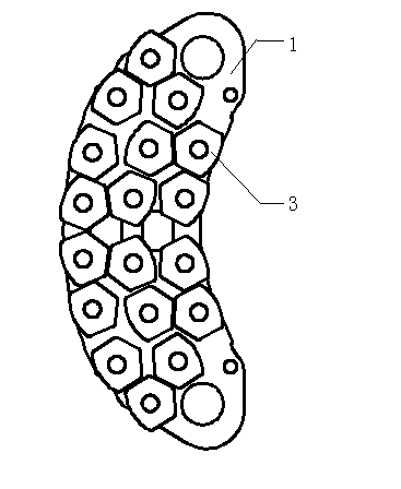
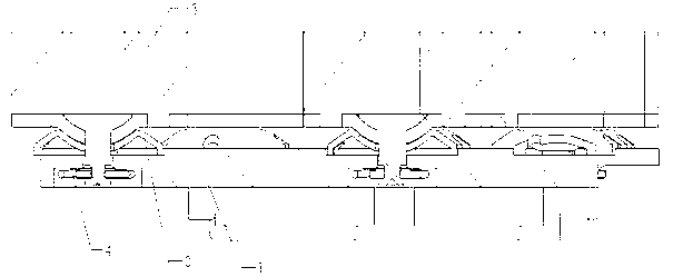
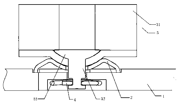
[0036] Such as Figure 1-8Shown is the floating brake pad of the present invention, which includes: a brake pad back plate 1 formed with a plurality of positioning holes 11; several friction blocks 3, which include friction parts 31 inserted into the positioning holes 11 The positioning part 32 and the support part 33 arranged between the friction part 31 and the positioning part 32, the support part 33 is a spherical structure, and the spherical surface of the support part 33 protrudes in the direction of the positioning part 32; Several circlips 4, the circlips are clamped on the positioning part 32, and the friction block 3 is connected to the brake pad back plate 1 with a certain floating amount; The elastic support piece 2 between the block 3 and the brake pad back plate 1, the elastic support piece 2 includes: a spherical support surface 21, which is attached and connected with the support part 33, and the bottom of the spherical support surface 21 is provided There is ...

Embodiment 2

[0046] The structure of this embodiment is basically the same as that of Embodiment 1, and the difference is that:

[0047] Such as Figure 9 As shown, in this embodiment, the spherical support surface 21 is composed of a section of spherical surface, and the spherical support surface 21 is in surface contact with the support portion 33 of the friction block 3, instead of the edge in the first embodiment. The spherical part c and the bottom spherical part d form the spherical supporting surface 21. In this embodiment, the arrangement of the spherical supporting surface 21 makes the processing of the elastic supporting sheet more convenient.


PUM


Abstract

The invention discloses a floating brake pad which comprises a pad back plate, a friction block, a clamp spring, an elastic support sheet arranged between the friction block and the pad back plate. The elastic support sheet comprises a spherical support surface and a support pawl on the outer side of the spherical support surface, wherein the spherical support surface is bonded with a spherical support part of the friction block, and a guiding hole suitable for a positioning part of the friction block to penetrate through is formed at the bottom center of the spherical support surface. The support pawl extend to the bottom of the spherical support surface from the periphery of the spherical support surface in the direction away from the guiding hole, the connection edge of the support pawl is connected with the periphery of the spherical support surface through a smooth transition section, and the support pawl and the support edge extend out of the bottom of the spherical support surface. The floating brake pad solves the problem that a pawl of the elastic support part of the existing brake pad is bent inwards instead of extending outwards, so that when stressed, the elastic support can extend outwards along the direction of the support pawl, and support of the corresponding part cannot fail.

Description

technical field [0001] The invention relates to a floating brake pad, which belongs to the technical field of train braking. Background technique [0002] At present, in high-speed train brakes, disc brake structures are usually used. The disc brake structure mainly includes a brake disc and a brake pad. The above-mentioned brake structure consumes the kinetic energy of the moving vehicle or equipment through the mutual friction between the brake disc and the brake pad to stop the train from moving. However, since the brake pads generally adopt the fixed connection mode of rivets, when braking, it is easy to appear that the friction block on the brake pads and the brake disc cannot be completely fitted together, so that the force cannot be evenly distributed. The role of the brake pads on the friction block and the brake disc, resulting in cracks, missing blocks, and defects at the high-stress point of the brake pads, resulting in local high-temperature areas, shortening th...

Claims


Application Information

Patent Timeline
Patent Type & Authority Applications(China)
IPC IPC(8): F16D65/092F16D65/097
Inventor 吴佩芳
Owner BEIJING TIANYISHANGJIA NEW MATERIAL
Why Eureka
Try Eureka