Thin roof ventilator

A kind of ventilator, thin technology, applied in the direction of roof ventilation, ventilation system, space heating and ventilation, etc., can solve the problems such as the reduction of the effective flow area of ​​the ventilator, the loss of ventilation ability of the ventilator, and the falling of external pollutants, etc., to achieve Prevent external airflow backflow and rainwater leakage, facilitate regular material replacement, and facilitate product maintenance

Active Publication Date: 2013-06-05
锦州鹏翔电力轻钢设备有限公司
View PDF8 Cites 10 Cited by
  • Summary
  • Abstract
  • Description
  • Claims
  • Application Information

AI Technical Summary

Problems solved by technology

According to the ventilation flow formula Q=μ F m3 / s, must For ventilation devices with specifications, the increase in overlap reduces the effective flow area F inside the ventilator, and the low (thin) shelter structure increases the ventilation resistance after increasing the exhaust air bypass flow, and the flow coefficient μ Reduced, these methods of strengthening wind shelter all reduce the ventilation flow Q, that is, the ventilation performance of the product decreases
[0005] In order to enhance the wind-shielding performance, CN202501595U discloses an assembled light roof ventilator with a translational valve plate device, but since the valve plate device is located at the air inlet at the bottom of the ventilator , when the valve plate is closed, the ventilator will lose its ventilation ability, and external pollutants are more likely to fall on the valve plate with the wind, and the falling snowflakes will melt and drip into the building, causing pollution in the building

Method used


Image

  • Thin roof ventilator
  • Thin roof ventilator
  • Thin roof ventilator

Examples


Embodiment Construction

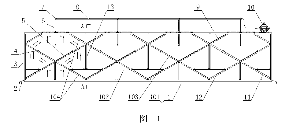
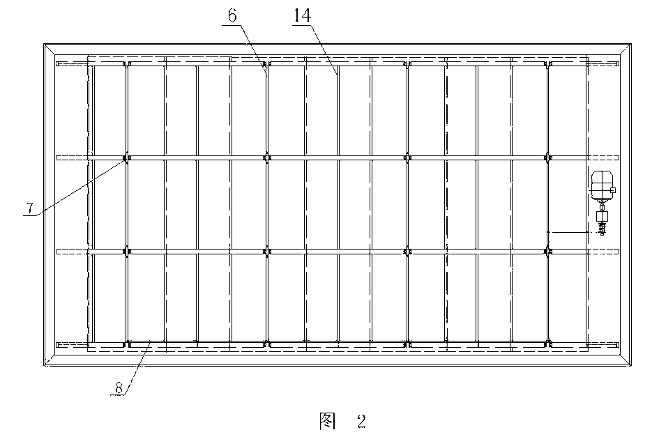
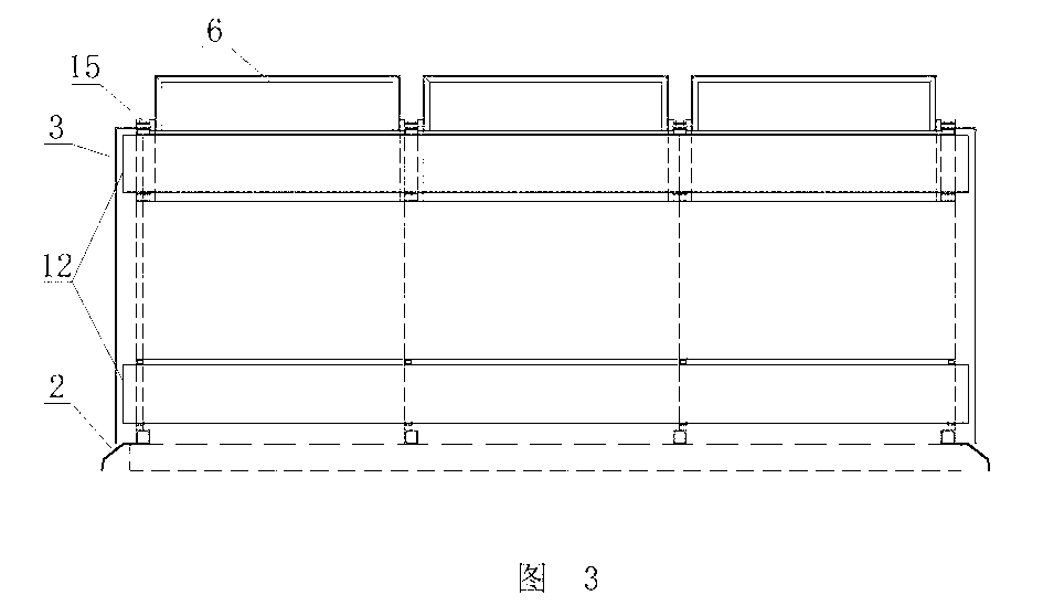
[0025] As shown in the figure, the thin roof ventilator includes multiple rows of parallel structural trusses 1 arranged on the roof vents. In this embodiment, four rows of structural trusses 1 are taken as an example. Rods 14 are connected, outer guard plates 3 are arranged around the multi-row structural trusses 1, flashing boards 2 are respectively arranged at the bottom of the multi-row structural trusses 1, and the flashings located at both ends of the structural trusses 1 The plate 2 is integrated with the outer guard plate 3 .

[0026] The structural truss 1 is composed of a lower cross bar 101 and a plurality of ventilation units 102 connected by profiles on the lower cross bar 101 , and this embodiment takes four ventilation units 102 as an example. The structural truss 1 is located between adjacent ventilation units 102 to form at least a triple V-shaped overlapping structure through its own profiles. In this embodiment, the triple V-shaped overlapping structure is f...


PUM


Abstract

The invention discloses a thin roof ventilator which comprises a plurality of rows of parallel structured trusses. Outer guard plates are arranged around the structured trusses. The thin roof ventilator is characterized in that each row of structured trusses is provided with a plurality of ventilation units. Middle V-shaped rain baffles are connected between opposite ventilation units in each row. Partitions, upper v-shaped rain baffles and V-shaped catch channels are arranged between each two adjacent rows of ventilation units respectively. Windshield valve plates are hinged to each two adjacent rows of structured trusses. The thin roof ventilator has the advantages that the thin roof ventilator has natural load-carrying capacity, base materials can be saved greatly, manufacturing and installation ways of products are simplified, standardization and popularization are easy; the thin roof ventilator has the function of automatically adjusting wind shielding, external air can be prevented from flowing back, rain is prevented from leaking, unattended ventilation can be achieved; the thin roof ventilator has the function of replacing a roof, allows for large-area ventilation and lighting for buildings, is effective in ventilation and lighting and is highly functional in wind shielding regulation.

Description

technical field [0001] The invention relates to a building energy-saving ventilation device, in particular to a thin roof ventilator. Background technique [0002] The demand for building energy-saving applications has stimulated the development and application of building natural ventilation technology products. In recent years, thin roof ventilators have gradually been selected by certain designs and users. A kind of roof ultra-thin streamline ventilator disclosed by CN201589368U and a kind of assembled light roof ventilator etc. disclosed by CN202501595U. [0003] However, the development of conversion technology has gradually become erroneous, and the original simple and economical natural ventilation product technology tends to be complicated: 1. The board molded special-shaped material technology used is not conducive to product standardization, popularization and popularization, and is not conducive to product material selection It is interchangeable with applicat...

Claims


Application Information

Patent Timeline
Patent Type & Authority Applications(China)
IPC IPC(8): F24F7/02F24F13/32E04D13/17
CPCE04D13/03F24F7/02E04D13/0325
Inventor 单连勤卢彤彤单晓晴宋凯宇刘可杨立年
Owner 锦州鹏翔电力轻钢设备有限公司
Why Eureka
Try Eureka