Thin ventilation skylight

A ventilation skylight and thin technology, applied in the direction of skylight/dome, roof, building components, etc., can solve the problems of no load capacity, rain and snow of the product, large building load and cost, etc., to reduce the production labor level and reduce the manufacturing cost. The effect of process difficulty and load capacity saving

Active Publication Date: 2016-04-13
锦州鹏翔电力轻钢设备有限公司
View PDF6 Cites 0 Cited by
  • Summary
  • Abstract
  • Description
  • Claims
  • Application Information

AI Technical Summary

Problems solved by technology

[0003] Since the application of thin skylights, there have been many technical problems: 1. The inherent lack of inertial buffer space for large skylights, and its triple overlapping rainproof structure relationship does not have the ability to prevent rain and snow from flowing backwards with the wind. When the weather is bad, the product often falls into the building. internal rain and snow phenomenon
2. The ventilation unit lacks the necessary support structure and cannot use low-strength light-transmitting materials, which affects the extended lighting function of the product
3. The connection structure between ventilation units has low strength and no load capacity. The product needs large structural material support to ensure its matching application with the roof structure
[0004] The above application problems reflect the irrationality of product technology
In practical applications, as a part of the building roof, the simple structure of the thin skylight does not mean that rain and snow seepage are allowed. At the same time, the large-scale foundation support structure will inevitably cause a large building load and cost in the large-area application of the product, making it impossible for thin technical products. Reflect the due small and light technical characteristics

Method used


Image

  • Thin ventilation skylight
  • Thin ventilation skylight

Examples


Embodiment Construction

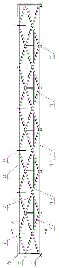
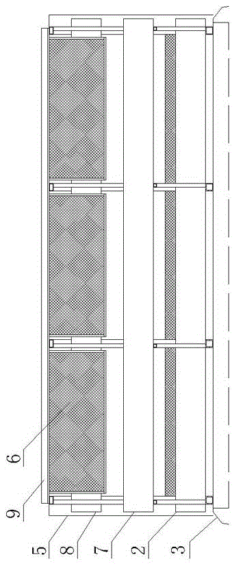
[0022] As shown in the figure, the thin ventilation skylight includes multiple rows of parallel structural trusses 1 arranged on the roof vents, the structural trusses 1 are arranged longitudinally along the roof vents, and each row of structural trusses 1 is composed of a rectangular frame 101 and a The rectangular frame 101 is composed of a plurality of ventilation units 102 connected by profiles. The upper ends of multiple rows of structural trusses 1 are connected to each other through vertical rods 9 evenly distributed above each ventilation unit 102 , and each row of structural trusses 1 is connected by bolts to facilitate manufacturing and installation. Multiple ventilation units 102 of each row of structural trusses 1 form an upper, middle and lower triple V-shaped overlapping structure through their own profiles. Between several columns of ventilation units 102 opposite to each other on the multi-row structural truss 1, there are three layers of V-shaped weather shiel...


PUM


Abstract

The invention discloses a thin ventilating skylight which comprises a plurality of rows of parallel structure trusses. Wind shields are arranged on the peripheries of the rows of structure trusses. The thin ventilating skylight is characterized in that each row of structure truss is provided with a plurality of ventilation units arranged side by side, three layers of V-shaped rain baffles are arranged between a plurality of columns of opposite ventilation units on the rows of structure trusses in a vertically staggered and overlapped mode, a certain of ventilation distances are kept between the rain baffles, unit separation nets are arranged between every two adjacent columns of ventilation units in a penetrating mode, rain blocking nets are arranged on the middle-upper portions of the columns of ventilation units located between adjacent structure trusses respectively, and the three layers of V-shaped rain baffles are led out from the structure trusses at the two ends. The thin ventilating skylight has the advantages that the rain entering angle can be reduced through the rain blocking nets, rain can be effectively buffered through the rain blocking nets and the unit separation nets, rain and snow can be prevented from flowing backwards and falling into a house in a splashing mode along with wind without increasing the overlapping size of rain baffles, the ventilation performance of the skylight is good, and the requirement for designed ventilation flow can be met.

Description

technical field [0001] The invention relates to building energy saving and green building material technology, in particular to a thin ventilation skylight. Background technique [0002] As a category of natural ventilation, open skylights that do not need to be opened and closed are perceived by people as a product with a simple structure, and are mostly used in industrial buildings that do not require high rigor. The open thin ventilation skylight in the national standard atlas "Ventilation Skylight" (05J621-3) is a combination of small ventilation units referring to the structure of large skylights. The ventilation capacity of the small ventilation unit is limited, so that the thin skylight must rely on increasing the amount of design to reflect the use function of the product. [0003] Since the application of thin skylights, there have been many technical problems: 1. The inherent lack of inertial buffer space for large skylights, and its triple overlapping rainproof s...

Claims


Application Information

Patent Timeline
Patent Type & Authority Patents(China)
IPC IPC(8): E04B7/18E04D13/03
Inventor 单连勤杨丽萍马力李歆昊韦福利杨立年王玲卢彤彤
Owner 锦州鹏翔电力轻钢设备有限公司
Why Eureka
Try Eureka