
A UHF electronic tag and its sensitivity configuration method

A technology of electronic tags and configuration methods, applied in instruments, computing, record carriers used by machines, etc., can solve the problems of long identification distance of ultra-high frequency electronic tags, easy to steal tag information, and complicated implementation schemes, so as to reduce the risk of being damaged. The risk of stealing, avoiding complex schemes, the effect of simple circuits

Active Publication Date: 2016-08-03
NATIONZ TECH INC
View PDF4 Cites 0 Cited by
  • Summary
  • Abstract
  • Description
  • Claims
  • Application Information

AI Technical Summary

Problems solved by technology

[0006] However, it is precisely because of the long recognition distance and high sensitivity of UHF electronic tags that they are easily misread by other card readers and increase the risk of tag information being easily stolen.
The current solution is mainly to control the receiving sensitivity of the card reader, but the implementation is more complicated

Method used


Image

  • A UHF electronic tag and its sensitivity configuration method
  • A UHF electronic tag and its sensitivity configuration method
  • A UHF electronic tag and its sensitivity configuration method

Examples


Embodiment 1

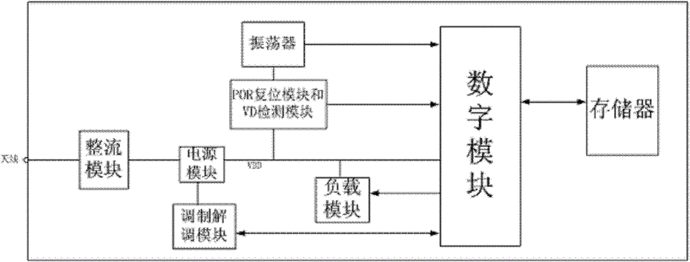
[0036] Please refer to figure 1 , a schematic structural diagram of Embodiment 1 of the UHF electronic tag of the present invention. In this embodiment, the power supply circuit includes: an antenna, a rectification module, a power supply module, a POR reset module, a VD detection module, and an oscillator. The antenna, the rectifier module, the power module, the digital module and the memory are connected in series in sequence, and the POR reset module and the VD detection module are connected in series with the oscillator and then connected between the power module and the digital module. The load module includes a load terminal and a control terminal, the load terminal is connected to the power module, that is, connected to the internal power supply VDD; the control terminal is connected to the digital module. The digital module increases the corresponding load on the power supply circuit by controlling the load module.

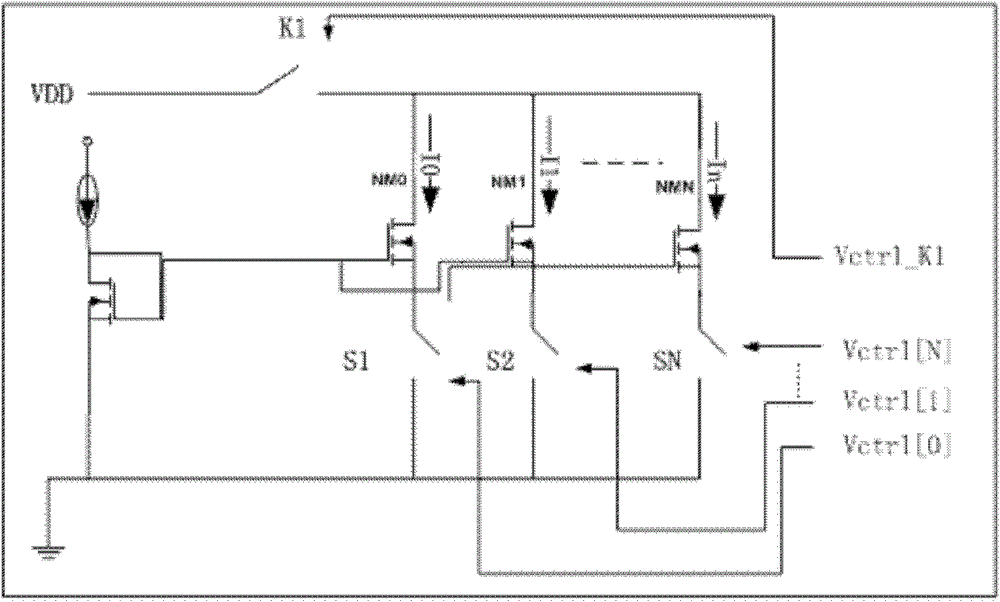
[0037] In this embodiment, the load module may als...

Embodiment 2

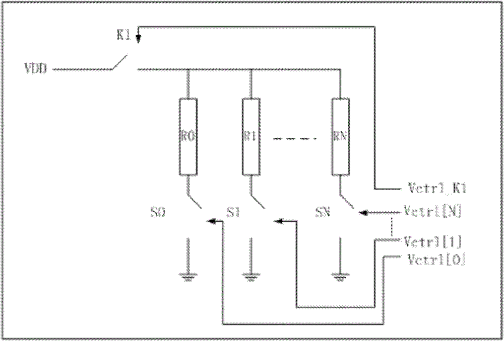
[0050] Please refer to Figure 5 , the structural schematic diagram of the second embodiment of the UHF electronic tag of the present invention and Image 6 , is a structural schematic diagram of the implementation of the load module resistance of the UHF electronic tag in Embodiment 2 of the present invention. In the load module in this embodiment, the control terminal is connected to the digital part, and the loading terminal is connected to both ends of the antenna. In this embodiment, because the antenna signal is an AC signal, there is only one internal structure of the load module, that is, the realization of multi-channel resistance loads in parallel. The control terminal of the load module controls the on-off of the branch switch.

[0051] This embodiment also provides a sensitivity configuration method, and the specific operation steps are the same as those in the embodiment, and will not be repeated here.


PUM


Abstract

The invention discloses an ultrahigh frequency electronic tag and a sensitivity configuration method of the ultrahigh frequency electronic tag. The ultrahigh frequency electronic tag comprises a rectifier module, a modulation-demodulation module, a power module, a power on reset (POR) resetting module, a voltage detector (VD) detection module, an oscillator, a memory, a digital module and a load module which is used for loading a power circuit. Through the ultrahigh frequency electronic tag and the sensitivity configuration method of the ultrahigh frequency electronic tag, control of sensitivity can be realized through a quite simple circuit, the situation that the ultrahigh frequency electronic tag is misread by other card readers due to the fact that the sensitivity is too high is avoided, and the risk that the tag information is stolen is further lowered.

Description

technical field [0001] The invention provides an ultra-high frequency electronic tag and a sensitivity configuration method thereof, in particular an electronic tag whose sensitivity is configured through a simple circuit and a configuration method thereof. Background technique [0002] The emergence of electronic tags marks the birth of a new identification technology application. With the development and maturity in recent years, its successful application in the field of Internet of Things has changed the way people interact with the world, which can be said to be a revolution. [0003] Electronic label technology is a non-contact automatic identification technology. It automatically identifies the target object and obtains relevant data through radio frequency signals. The identification work does not require manual intervention. Therefore, it is widely used in industrial production automation, supply chain management, logistics cargo tracking, transportation fields of ...

Claims


Application Information

Patent Timeline
Patent Type & Authority Patents(China)
IPC IPC(8): G06K19/077
Inventor 石道林李鸿雁
Owner NATIONZ TECH INC
Learn More