
Lubricant dispenser

A technology of lubricants and distributors, which is used in lubricating parts, engine lubrication, signal processing, etc., can solve the problem of unsatisfactory environmental costs, increasingly complex electronic control of lubricant distributors, and inability to guarantee lubricant distributors, etc. question

Active Publication Date: 2012-02-01
PERMA TEC
View PDF7 Cites 11 Cited by
  • Summary
  • Abstract
  • Description
  • Claims
  • Application Information

AI Technical Summary

Problems solved by technology

This is unsatisfactory either for environmental reasons or for cost reasons
Another disadvantage is that after a long period of storage of the lubricant dispenser the battery is partially discharged before the lubricant dispenser is put into service, since the battery is already supplying the electronic control unit in an inert state
Sometimes it is not guaranteed that the lubricant dispenser will still work as specified over long application times due to partial discharge caused by standing
[0003] Increasingly complex electronic control of lubricant distributors with electrochemical gas drives

Method used


Image

  • Lubricant dispenser
  • Lubricant dispenser
  • Lubricant dispenser

Examples


Embodiment Construction

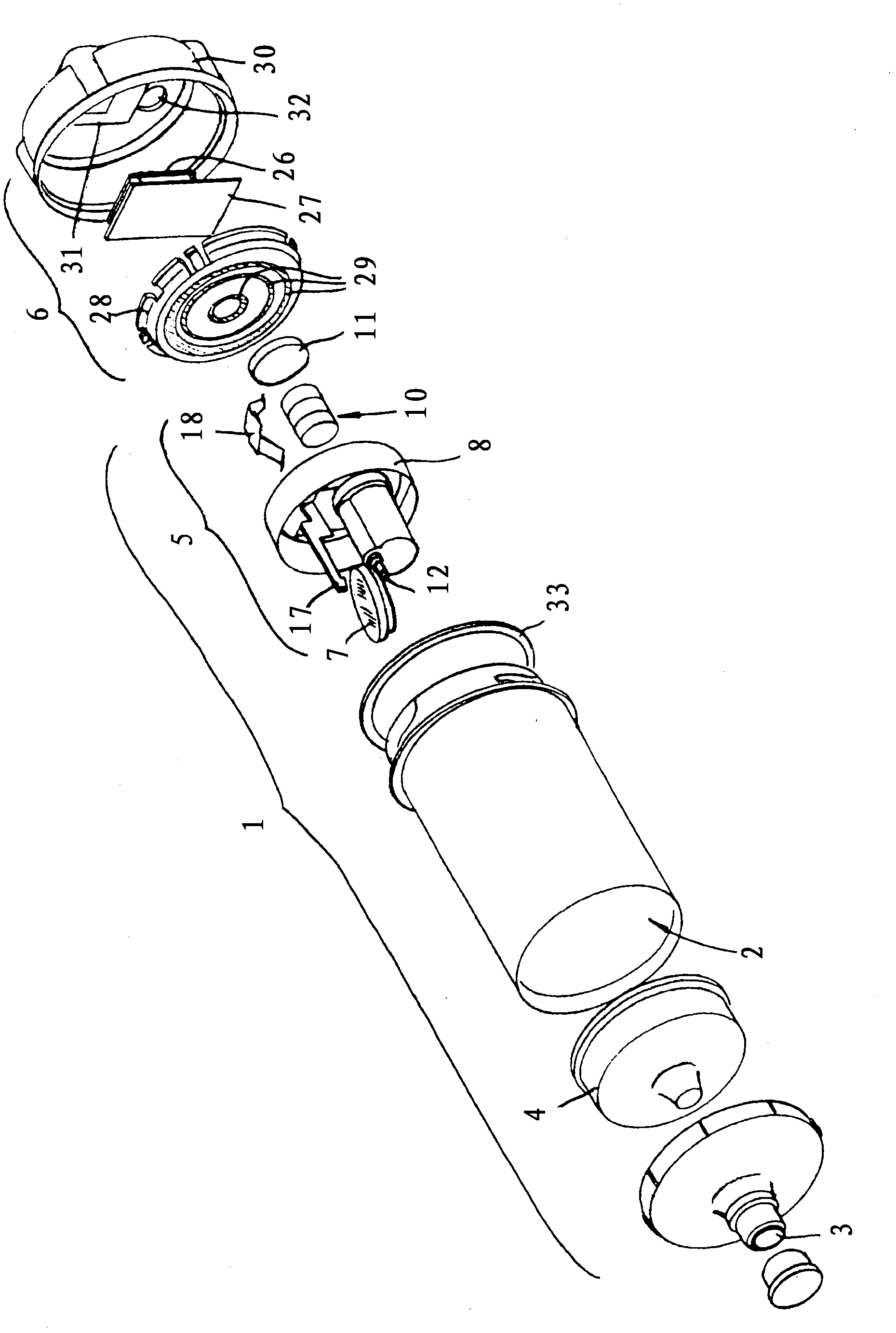
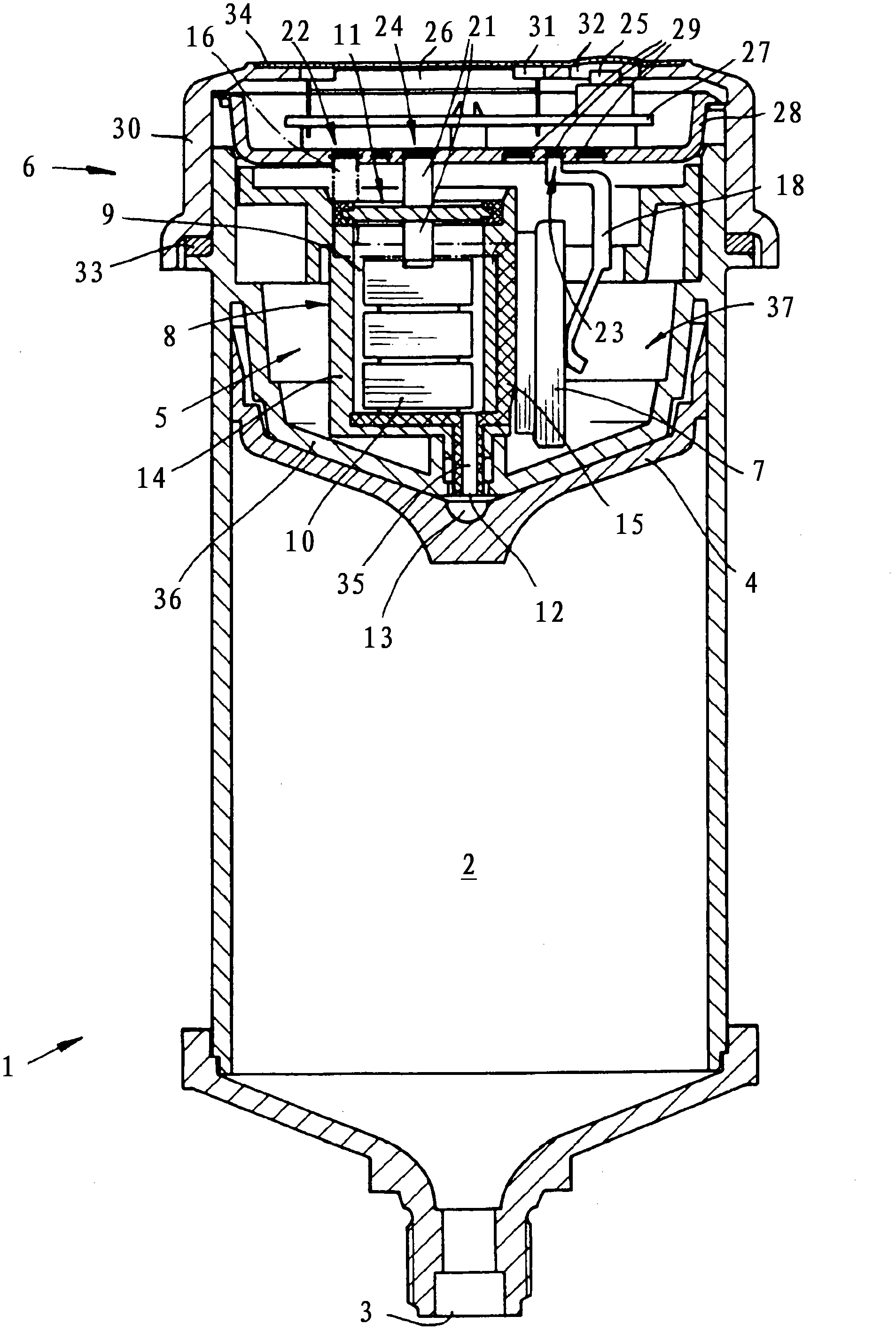
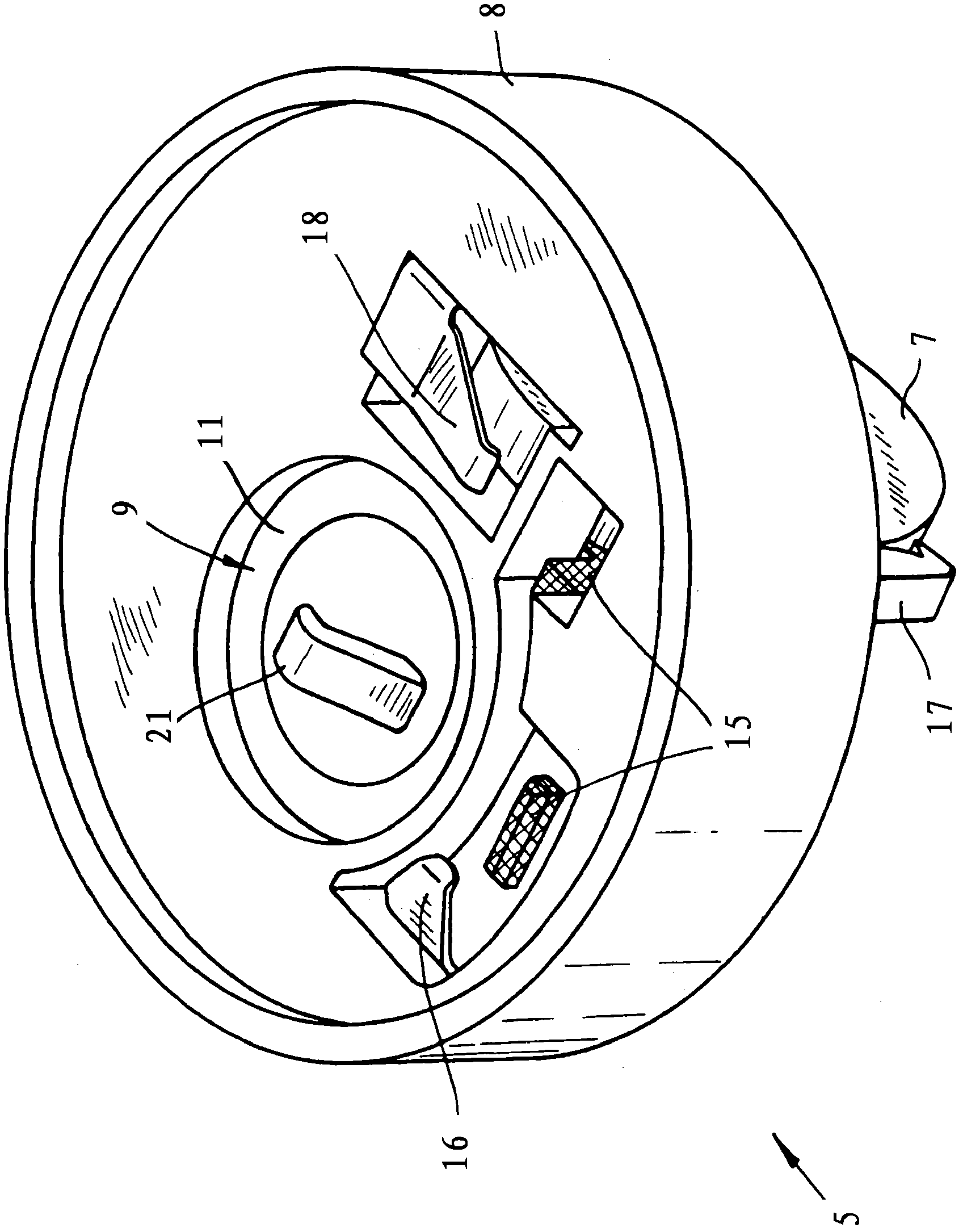
[0017] The basic structure of the lubricant dispenser shown in the drawings includes a lubricant cartridge 1 , an electronic control unit 6 for controlling electrochemical gas generation, and a drive battery 7 for powering the electronic control unit 6 . The lubricant cartridge 1 comprises a lubricant reservoir 2 provided with a lubricant outlet 3 , a piston 4 and a gas generator unit 5 for electrochemical gas generation. The electronic control unit 6 is detachably connected to the lubricant cartridge 1 as a separate and reusable unit and has electrical contact elements which are in connection with the electrical terminals of the gas generator unit 5 . The drive battery 7 is fastened inaccessibly on the support 8 of the gas generator unit 5 . The electronic control unit 6 does not have its own power supply, so only by mounting the electronic control unit 6 on the lubricant cartridge 1 is the electrical circuit assigned to the gas generator unit 5 closed and the electronic cont...


PUM


Abstract

A lubricant dispenser having a cartridge, a wall in the cartridge defining therein a lower chamber and an upper chamber, and a piston subdividing the lower chamber into a lower lubricant compartment and an upper gas compartment. The cartridge has an outlet opening into the lower lubricant compartment. A body of fluent lubricant fills the lower lubricant compartment. A housing in the upper chamber holds a gas generator connected through the wall to the gas compartment and electrically energizeable to generate gas and pressurize the gas compartment. A battery is secured to the housing. An electronic controller removably mounted in the upper chamber has electrical contacts connectable to the battery and to the gas generator. It is powerable by the battery for operating the gas generator and thereby pressurizing the gas compartment, moving the piston, and forcing the lubricant out of the outlet.

Description

technical field [0001] The invention relates to a lubricant dispenser comprising a lubricant cartridge, an electronic control unit for controlling electrochemical gas generation and a drive battery for at least powering the electronic control unit, said lubricant cartridge comprising a lubricant Lubricant reservoir for lubricant outlet, piston and gas generator unit for electrochemical gas generation. Background technique [0002] A lubricant dispenser (applicator) of the described character is disclosed in DE 10 2005 035 452 A1. The gas generator unit, the electronic control unit and the battery for power supply are integrated in the lubricant cartridge and installed in a closed housing. The lubricant cartridge is a single-use item and is discarded as a whole, including the electronic assembly, after the lubricant reservoir is emptied. This is unsatisfactory neither for environmental reasons nor for cost reasons. A further disadvantage is that after a prolonged storage o...

Claims


Application Information

Patent Timeline
Patent Type & Authority Applications(China)
IPC IPC(8): F16N11/10F16N29/02
CPCF16N11/10F16N2230/02F16N29/02
Inventor E·罗纳R·莫泊
Owner PERMA TEC
Learn More