Winding method of cored coil and winding device of cored coil

A winding device and a cored coil technology are applied in the field of cored coil windings and cored coil winding devices to achieve the effect of rapid winding

Active Publication Date: 2015-08-05
NITTOKU ENG CO LTD
View PDF5 Cites 0 Cited by
  • Summary
  • Abstract
  • Description
  • Claims
  • Application Information

AI Technical Summary

Problems solved by technology

However, when one end of the wound member is supported on the winding jig to rotate it, if the wound member is rod-shaped and formed so that the wound member does not have a flange that limits the winding width, Since there is no place where the winding width of the other side of the wound member should be limited, there will be a disadvantage that the wire cannot be wound at the expected position of the wound member with the expected winding width.

Method used


Image

  • Winding method of cored coil and winding device of cored coil
  • Winding method of cored coil and winding device of cored coil
  • Winding method of cored coil and winding device of cored coil

Examples


Embodiment Construction

[0027] Next, the best mode for implementing the present invention will be described based on the drawings.

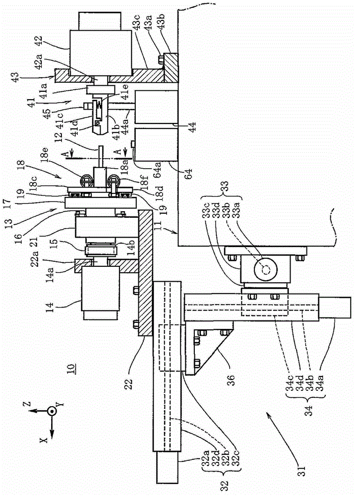
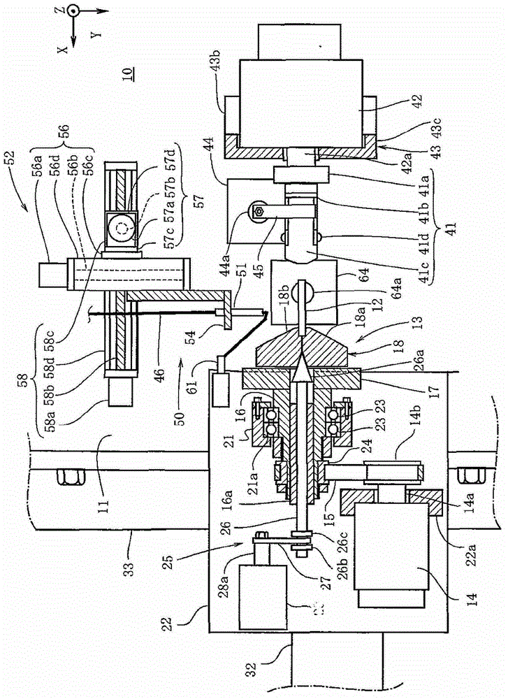
[0028] figure 1 and figure 2 The winding device 10 for the cored coil of the present invention is shown in . Among them, the three axes X, Y, and Z that are orthogonal to each other are set, and the X axis is set to extend horizontally, the Y axis is set to extend along the horizontal front-back direction, and the Z axis is set to extend along the vertical direction. Thus, the winding device 10 of the present invention will be described. The winding device 10 of the present invention includes a base 11 and a first winding jig 13 configured to support one end of a member 12 to be wound and to be rotatable together with the member 12 to be wound. The base 11 is configured in a box shape capable of being installed at an installation location, and a not-shown moving roller and a stopper member for fixing to the installation location are installed at the lower portion. ...


PUM


Abstract

A coiling method and a coiling device for a cored coil are capable of coiling a wire effectively onto a coiled part at an expected position with an expected winding width, and fully increasing the speed of coiling. The coiling device comprises a first coiling clamp supporting one end of the coiled part and rotating to enable a dyke-shaped coil formed at one end side of the coiled part; a second coiling clamp supporting the other end of the coiled part and rotating to enable the wire to be coiled from the dyke-shaped coil to the other end of the coiled part; a coiling clamp movement mechanism capable of moving any one of the first and second coiling clamps towards three axial directions. The coiling method includes a first coiling procedure enabling the first coiling clamp supporting one end of the coiled part to rotate together with the coiled part to make the dyke-shaped coil be formed at one end side of the coiled part and a second coiling procedure enabling the second coiling clamp supporting the other end of the coiled part to rotate together with the coiled part to make the wire be coiled onto the coiled part between the second coiling clamp and the dyke-shaped coil.

Description

technical field [0001] The present invention relates to a cored coil winding method and a cored coil winding device for obtaining a cored coil such as a timepiece coil by winding a wire around a wound member as a core material. Background technique [0002] Conventionally, as a winding method of winding a wire around a rod-shaped member to be wound as a core material, there is known a winding method of a cored coil in which two winding jigs are provided to face each other, Increase or decrease the interval of these two winding jigs to obtain the same width as expected. When performing this increase or decrease, the wire is wound on the part held by the two winding jigs of the winding part (for example, refer to the patent Literature 1). In this winding method, by winding the wire around the portion of the winding member clamped by the two winding jigs, even if the winding member does not have a flange that limits the winding width, for example, It is also possible to relia...

Claims


Application Information

Patent Timeline
Patent Type & Authority Patents(China)
IPC IPC(8): H01F41/06
Inventor 近藤功治
Owner NITTOKU ENG CO LTD
Why Eureka
Try Eureka