Resonant circuit current limiting protection method and device
A resonant circuit and resonant current technology, applied in the field of communication, can solve the problem of the voltage stress exceeding the standard of the full bridge tube, and achieve the effect of improving reliability
- Summary
- Abstract
- Description
- Claims
- Application Information
AI Technical Summary
Problems solved by technology
Method used
Image
Examples
Embodiment 1
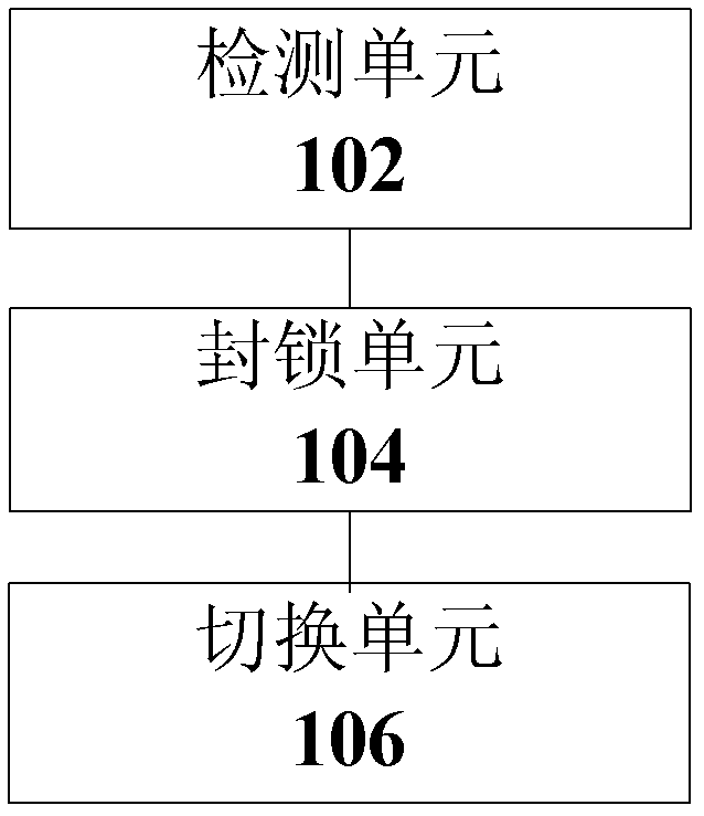
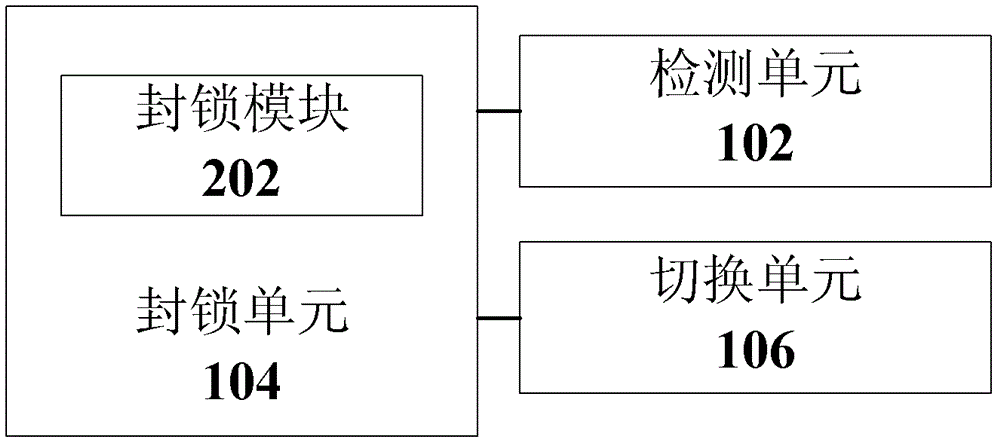
[0031] Such as figure 1 As shown, the present invention provides a preferred resonant circuit current limiting protection device, which includes: a detection unit 102 for detecting the voltage at both ends of the sampling resistor through which the resonant current flows in the resonant circuit; a blocking unit 104 for When it is detected in the current resonance cycle that the voltage across the sampling resistor is greater than a predetermined threshold, the drive of the resonance circuit is blocked; the switching unit 106 is used to switch the resonance circuit from the constant voltage mode when the next pulse width modulation cycle arrives switch to output current limit mode.
[0032] In the above-mentioned preferred embodiment, by adding a strategy in the intelligent unit to make the LLC resonant converter enter the current-limiting loop immediately after the wave-by-wave current limit is detected, the primary current is quickly reduced to within the threshold, and the p...
Embodiment 2
[0041] Based on the devices and circuits shown in 1-7, the present invention also provides a preferred resonant circuit current limiting protection method, such as Figure 8 As shown, the method specifically includes:
[0042] S802: detecting the voltage across the sampling resistor through which the resonant current flows in the resonant circuit;
[0043] S804: When it is detected that the voltage across the sampling resistor is greater than a predetermined threshold in the current resonance period, blocking the drive of the resonance circuit;
[0044] S806: Switch the resonant circuit from the constant voltage mode to the output current limiting mode when the next pulse width modulation period arrives.
[0045] In the above-mentioned preferred embodiment, by adding a strategy in the intelligent unit to make the LLC resonant converter enter the current-limiting loop immediately after the wave-by-wave current limit is detected, the primary current is quickly reduced to within...
Embodiment 3
[0054] The present invention provides a preferred embodiment to further explain the present invention, but it should be noted that the preferred embodiment is only for better describing the present invention and does not constitute an improper limitation of the present invention.
[0055] The present invention will be further described in detail below through specific embodiments and in conjunction with the accompanying drawings.
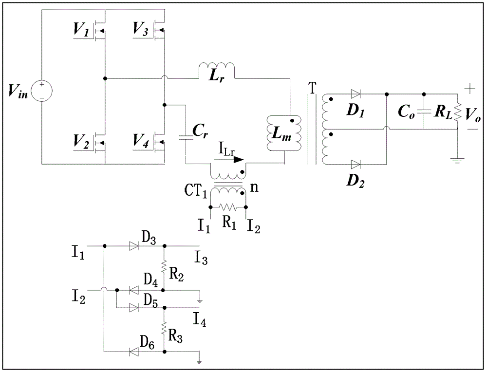
[0056] Such as image 3 As shown, an LLC resonant circuit includes a resonant inductor Lr, a main transformer T, a resonant capacitor Cr, main power switching devices V1, V2, V3 and V4, and secondary power Schottky diodes D1 and D2.
[0057] The resonant current detection circuit includes: current transformer CT1, magnetic reset resistor R1 of CT1, diodes D3, D4, D5 and D6. Preferably, the diodes use fast recovery diodes or Schottky diodes and current sampling resistors R2 and R3. The resonant circuit is connected to a DC input voltage Vin, the ma...
PUM
 Abstract
Description
Claims
Application Information
 - R&D
- Intellectual Property
- Life Sciences
- Materials
- Tech Scout
- Unparalleled Data Quality
- Higher Quality Content
- 60% Fewer Hallucinations
Browse by: Latest US Patents, China's latest patents, Technical Efficacy Thesaurus, Application Domain, Technology Topic, Popular Technical Reports.
© 2025 PatSnap. All rights reserved.Legal|Privacy policy|Modern Slavery Act Transparency Statement|Sitemap|About US| Contact US: help@patsnap.com


