Distributed power generation multilevel converter and its modulation method

A distributed generation, multi-level technology, applied in the direction of converting AC power input to DC power output, electrical components, output power conversion devices, etc., can solve the problems of difficult switch selection, limited expansion and practical application, etc. The effect of voltage gain

Active Publication Date: 2022-07-22
ZHENGZHOU UNIV
View PDF0 Cites 0 Cited by
  • Summary
  • Abstract
  • Description
  • Claims
  • Application Information

AI Technical Summary

Problems solved by technology

However, as the voltage stress on the H-bridge of scalable switched-capacitor multilevel converters increases with output voltage, the selection of switches becomes difficult, which limits the scaling and practical application of such converters.

Method used


Image

  • Distributed power generation multilevel converter and its modulation method
  • Distributed power generation multilevel converter and its modulation method
  • Distributed power generation multilevel converter and its modulation method

Examples


Embodiment 1

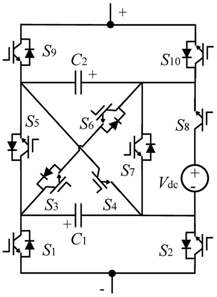
[0052] like figure 1 As shown, a distributed generation multilevel converter is set at the DC voltage source V dc and load, including forward bridge arm, reverse bridge arm, switched capacitor unit and switch tube S 8 ;

[0053] The switched capacitor unit includes a capacitor C 1 ,capacitance C 2 ,turning tube S 3 ,turning tube S 4 ,turning tube S 5 ,turning tube S 6 and switch tube S 7 ; the switch tube S 5 the emitter with the capacitor C 2 negative connection, the switch tube S 5 the collector of the capacitor with the C 1 The positive connection of the switch; the switch tube S 7 the collector of the capacitor with the C 2 the positive connection of the switch tube S 7 the emitter with the capacitor C 1 The negative pole is connected; the switch tube S 6 The collector of the capacitor is connected to the C 2 the positive pole of the switch tube S 6 The emitter is connected to the switch tube S 3 the emitter, the switch tube S 3 The...

Embodiment 2

[0072] The invention also provides an expandable distributed power generation multi-level converter, Figure 14 As shown, the multilevel converter further includes a plurality of switched capacitor units, and the switched capacitor units are connected in parallel at both ends of the forward bridge arm and the reverse bridge arm. The multi-level converter is provided with m (m=1, 2, . level.

[0073] The multi-level converter only needs to increase the switched capacitor unit when expanding, and the output voltage gain increases with each additional switched capacitor unit. V dc , the output level increases by 2, when the output voltage is n V dc , the number of output levels is 2n+1.

[0074] It should be noted that the maximum voltage stress borne by the switching device of the multi-level converter does not increase with the expansion of the switched capacitor unit, and is still 2 V dc . Therefore, the present invention effectively solves the technical problem of exc...

Embodiment 3

[0077] This embodiment provides a specific implementation of a distributed generation multi-level conversion system, the distributed generation multi-level conversion system includes a controller and a multi-level converter, and the multi-level converter is an embodiment The distributed generation multilevel converter described in 1. The controller is connected in communication with the multi-level converter, so as to realize the adjustment of the working mode by adjusting the on-off of the switch tube.

[0078] The controller executes the steps of the modulation method for the distributed generation multilevel converter described in Embodiment 1 when the controller controls the operation of the switch tube in the distributed generation multilevel converter.

[0079] In this embodiment, the controller verifies the distributed generation multilevel converter and its modulation method through simulation according to the above modulation method. Settings: The DC input voltage is...


PUM


Abstract

The present invention provides a distributed generation multi-level converter, which is set at the DC voltage source V dc and load, including forward bridge arm, reverse bridge arm, switched capacitor unit and switch tube S 8 ; The switched capacitor unit includes a capacitor C 1 ,capacitance C 2 ,turning tube S 3 ,turning tube S 4 ,turning tube S 5 and switch tube S 6 ;Forward bridge arm includes switch tube S 9 and switch tube S 10 ,turning tube S 9 The emitter is connected to the capacitor C 2 negative pole, switch tube S 10 The collector is connected to the capacitor C 2 positive, switch tube S 9 collector and switch tube S 10 The emitter of the multi-level converter is connected as an AC voltage output end of the multi-level converter; the reverse bridge arm includes a switch tube S 1 and switch tube S 2 ,turning tube S 1 The collector is connected to the capacitor C 1 positive, switch tube S 2 The emitter is connected to the capacitor C 1 negative pole, switch tube S 1 The emitter and switch tube of S 2 The collector is connected as another AC voltage output terminal of the multi-level converter.

Description

technical field [0001] The invention relates to the fields of power electronics and electric energy conversion, new energy power generation, medium and low voltage flexible power distribution, etc. In particular, it relates to a distributed power generation multilevel converter and a modulation method thereof. Background technique [0002] In recent years, due to the aggravation of environmental pollution and the continuous reduction of renewable resources, the development and utilization of clean, non-polluting renewable energy has received more and more attention. In renewable energy power generation such as photovoltaic power generation, a DC-DC converter is required to increase the voltage before performing inversion. Therefore, the DC-AC multilevel converter with boost capability is also the focus of research. Multilevel converters play an important role in renewable energy conversion due to their high output power quality, low voltage stress on switching devices, and ...

Claims


Application Information

Patent Timeline
Patent Type & Authority Patents(China)
IPC IPC(8): H02M7/483H02M7/5387
CPCH02M7/483H02M7/53871H02M1/007H02M7/4835
Inventor 王要强库若含王明东王克文章健梁军
Owner ZHENGZHOU UNIV
Why Eureka
Try Eureka